In this new blog article I’ll show you how to properly set your Element and its tanks in the best way! I’ll also give you some advise to avoid magnetic sensibility and to prevent from vibrations while you are on stage.
2 innovative ways to mount your tanks
Let’s begin with one of the main innovation of the Element, shall we ?! Most of spring reverb pedals come with huge housings because of the constraint of the springs size itself. So we simply decided to split the cumbersome part from the effect pedal. So basically, on one hand we got the pedal that process the sound and send it to the springs, and on the other hand we got various spring tanks that process the signal. Both are connected thanks to a RCA to mini jack cable which transmits the signal between them.
Under the pedalboard
This set up is the first one we pointed out when we launched the Element. Hide the tank underneath, and leave the pedal above! Then we just have to connect them with the cable and here we go! On the top we just have the cumbersome of a classic effect pedal and under we can put pretty big tanks considering the size of its pedalboard. Wonderful, isn’t it?
In the below example we’re using the screws set provided and the rubber bumpers, simply because it’s the best technique to absorb bumps and vibrations. But you can also use clamps on Pedaltrain…
Prefer the latest generation of power supplies using switch-mode, like the Strymon ones for example, or the one we’re currently developing!
If you have one as shown on the above video, that use a transformer and rectifying system (very old but damn efficient), here the Cioks DC-10. Connect the red plug as far as possible from the power supply, because it’s on the red part that the transducer is sensitive to noise! Noise which is by the way, coming from the power line cable going to the power supply transformer.
In its cab
For a long time, combo amps that embed a spring reverb, place their spring tank under the speaker. Well, we’re going to do the same thing!
Screw Le Bon, Le Brute, or Le Truand, your choice! (After all, Le Truand spring tank is the one that is used for the reverb from our legendary Fender amps.)
Use the RCA-mini jack cable supplied to connect to the tank to the pedal. We can go up to 20m (21.83 yards!!), proved!
Attach the pedal on the pedalboard.
This method in particular is the most universel, we ALL have a cab on stage and it can deal with every tanks! Except if you’re creating your sound only using IRs, but that’s another story… Ho, wait, you also use pedals? Go, on tell your story!
In this configuration, the tank is far from any electrical socket, goodbye parasites! We have a better resulting sound, but it’s also less sensitive to any mechanical pertubation. Just use some wood screws, the provided bumpers and a long cable!
Stay safe!
60 cycle, your old friend
As described in our article How Spring Reverb Works, we have to avoid at all costs to get the RCA cable near from the power supply cable, does not sound nice. Also, keep the red connector far from any 60 cycle power socket or power transformer.
To do so, follow the 2 possible technique I showed you, or just put it on top of the pedalboard! And then you’ll NEVER get bothered by the 60 cycle! If you got any problem, do not hesitate, leave a comment, send an email. We’re here to help!
Dear bumpers!
As you may have noticed, on all the tanks that were delivered to you, 2 or 4 rubber bumpers are snapped on it. Keep them! They absorb the soft to medium vibrations.
Now you can switch on and off your pedals on stage, without any vibrations, even if you love to stomp them hard!
But don’t worry, we’ll still be able to remember the good old chbouigouuingoung that we love so much! Instead of hitting the pedalboard vertically, hit it horizontally to make it move!
At least with this technique, you choose when it rings, and you can even do in rythm.
Some pedalboards we couldn’t resist!
Swan and Alex at GAK embodied by Joss AllenDan&Mick’s pedalboard from That Pedal Show while shooting their comparative video on spring reverbsCorey’s pedalboard from the USA, just the Element and La BruteRich’s pedalboard from the USA, the Element with La Brute tank under the pedalboard!Our pedalboard on trial at Guitare au Beffroi in Paris, with Le Bon on its surface, and La Brute underPedalboard from a scottish client, as complete as it should be!
Subscribe !
Subscribe to our newsletter and you’ll receive a 10% discount for your first order, you’ll be notified of all the news before anyone else, and you’ll participate to our private sales!
Of course, we don’t send that much mails! Maximum twice a month, and if you get bored of receiving them, you’re 100% free to unsubscribe, and your data will be gone from our server, forever!
In this article I will tell you how to read a Bill Of Materials (BOM), identify your kits components and how to correctly place them on your Printed Circuit Board (PCB).
Before going any further, we’re going to get some reminders on PCBs, BOM, and every piece of equipment you need to work well. If you’re already familiar with this stuff, you can skip the explanation and go to the tutorial part by clicking here.
what you need on your bench
recommended tools
The dreaming bench
Here’s a list of tools you’re gonna need. You don’t have to get all of these tools in particular but it would help a lot.
my favourites
A multimeter, it’s a very useful measurement equipment for any electronic advice. Resistor, voltage, current, capacity… And the prices go within a very large range. The good news is that you can find some pretty decent ones. So here’s our little selection : This one is on sale for 14$ and this one for 30$. It’s up to you considering how often you will use it. Just know that you can deal the tutorial without any mulitmeter if you learn the resistor color code!
A PCB holder, I admit this is luxury but I love it! Secure your PCB bewteen the 2 clamps and putting the components becomes much easier. You can also make it without this equipment by working directly on the table but it’s less convenient.
A storage cabinet for your components. It allows you to sort them by values. The point is to deal directly with our suppliers and to order 100 pieces of each resistors, and never have to sort them again ! If you’re to realize pedals quiet often, this way is much more economic and time saving.
classics
A round nose plier, it’s a very useful tool we use on a daily basis. It allows you to properly fold components legs and to get a good grip on cables once they’re deep into the housing. It’s a plier, you can hold approximately everything with it. At this time of the building, it is not essential, but you will need it in the following tutorials. So don’t waste time!
A 3rd hand holder will facilitate the wiring of the switchs and pots in the next tutorial. You can use it not only for wiring but also to hold your card while mounting the components.
If the pedal is the body, the PCB is the heart! It contains all the connections to give life to the schematic
how do we make a pcb
Exemple de PCB
Most of PCBs are made in Asia, you just have to be specific to get what you want. For your own prototypes, I’d advice you to go to PCB Way. It is more than enough if you build PCBs from time to time.
Our PCBs are made from a FR4 plate (some sort of plastic fiber). On each side, the manufacturer adds a copper layer. Then only our routings, that we make with a software, are kept in the copper layer. Afterwards a milling machine drills the plate, and a surface treatment metallizes the holes. The plate is then coated with a thin gold layer that protects the whole card from corrosion. Finally, instructions are drawn in a white writing to indicate component placements, board serial number, etc…
On the left, our computer drawn typon, on the right, a double sided layer sectional view.
how to make your own pcb
You may have guessed, to make a PCB, you absolutely need a good technical drawing. That’s what we call a typon, and we get it using a CAD software. Our team works with Eagle PCB, the interface is user-friendly and there are a lot of available librairies. Then, when we discover new sounds in the R&D department; we go onto this sofwtare, draw the schematic, and make the routing.
The electronic schematic of Fuzz Face pedal before turning it into a PCB
Indeed, The schematic is a visual and very simple to understand form. Anyone can understand it very quickly and it’s a necessary step before making the PCB. We can also transfer the schematic to another software and simulate how it works.
the bom (bill of materials)
Once we receive the PCBs, all we have to do is to export the BOM from the software. It is actually a list containing all the components that must be on the board. We know what to choose, what it is, and where to solder!
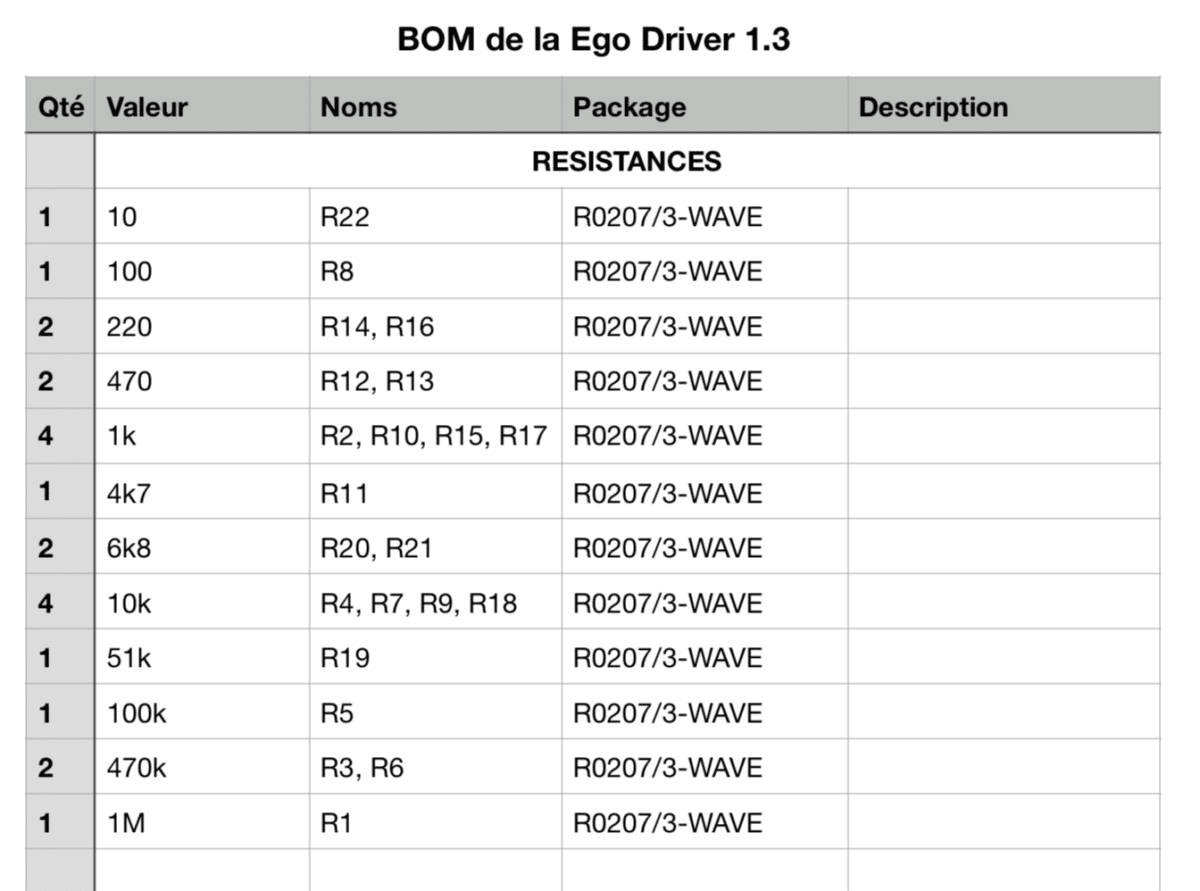
Exemple avec une partie de notre BOM pour le kit de la Ego Driver
I’ll explain to you how to read it :
The title. You ABSOLUTELY need the right BOM for the right PCB ! The serial number is written on it, check twice that everything is clear before staring.
Column Quantity, quite obvious isn’t it. That’s how many of each components you need. So you can take all of them at once. Then you just have to place them to their location. Save some time !
Column Value, as we sorted the components by their values, this column tells you which one you need to take.
Column Noun. Once you hold your component, you have to check the footprint on the board to know where to mount it. See below to learn more.
Column Package, it’s a technical information about the product line to choose. Convenient when you’re used to make DIY projects and that you want to order you components by yourself.
Because we try to be nice with you, we cut the BOM document in several sections. First section is “RESISTORS”, then “CAPACITORS”, etc… It is clear, you can’t get lost and sections are in logical order. So you’ll see next that there are a bunch of types of components and you’ll enjoy this attention to detail.
mounting of the electronic components
In this part you’re gonna discover how to mount each of the components on your board! At the same time I’ll tell you how where they come from, how to identify them and why we use them.
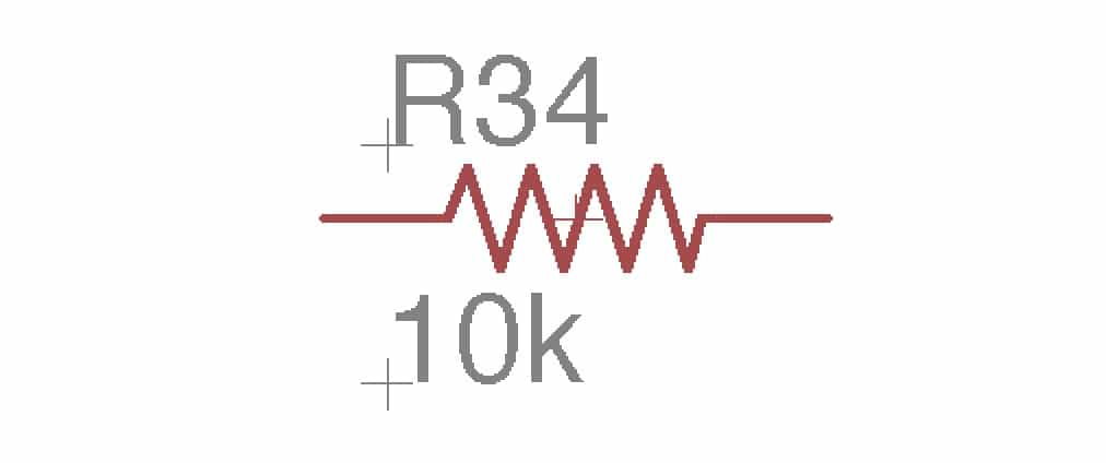
resistors
Resistor symbol on a schematic.
1/4W Xicon film metal resistor
color code method
Whenever you have a pedal, you have resistors. They resist to the current flow in a circuit (hence their name). And if you learn a bit more about electronics, you’ll learn that you can do much more functions !
To identify a resistor value, given in Ohms (Ω), manufacturers agreed on a common color code. This color code is made thanks to color rings on the resistor, which translate into values.
The color code with 2 exemples
For your information, we relieve mathematical writings such as :
k = kilo = 10^3 = 1 000
M = mega = 10^6 = 1 000 000
To give you a order of magnitude, values betwenn 1Ω and 1kΩ are considered small. Between 100kΩ et 2.2MΩ is considered super large!
multimeter method
You want to go easy ? Switch on your mulitmeter on Ohmeter mode and read their value thanks to the probes!
A multimeter and a resistor. There is just to read what’s written on the screen!
okay then, but why ?
When you’ll get your FX Teacher kit delivered, you’ll have a bag with different value resistors mixed. You’ll eventually need to know which one is the 10kΩ resistor to put on R4!
2 Options :
Each time you find a resistor, measure it and mount it on your board. Not to complicated ! But it’s a another step beside. I used to do my first boards like that, but not anymore!
Or you can use a storage cabinet to store a lot of resistors in it, from various values. By buying them by 100 it becomes much more affordable and they are already sorted. Just store each references in each drawer and this is done! This quantity might seem to be a lot at first, but you won’t have a lot left after making less than ten pedals.
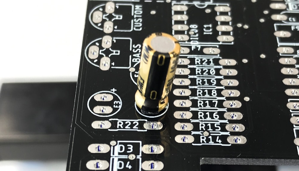
how to mount them on board
A resistor mounted on R19. A little bit twisted due to many manipulations, but there!
We fold the resistor legs with a nose plier before placing it
why this kind of resistor and not another one?
There are dozens of different resistor types and manufacturers ! While some still like carbon resistor for their vintageness, they are not very precise and they are noisy. So we trusted the brand Xicon with their metal film resistors. They offer a much more precise value, with a 1% error rate. And, a thermic sensibility of 50ppm which is ridiculous. We chose a line with a power handling of 1/4W, which is more than enough for pedal manufacturing.
With this line I’m sure not to alter the quality of my electronic design! This is why we trust them for the production of our Anasounds pedals for years.
capacitors
The different types of capacitors with their electronic symbols. About the names, we use C for ceramic, F for film and E for Electrolytic.
operating principle
capacitor physics
A capacitor is made of 2 metallic plates separated by an insulator. When we apply a voltage on its terminals, the 2 electrodes get positively loaded on one side, and negatively loaded on the other one. Once we release this voltage, both poles are going to discharge energy in the circuit. Considering their value, this amount will be released quicker or slower. A current is generated in the circuit depending on the formula i(t) = C * d u(t)/dt.
i is the current injected in the circuit. C is the capacity of the capacitor. u is the voltage on the capacitor terminals.
the types of capacitors
The first domain of improvement focused on by scientists was the insulator. We don’t use any capacitor for any situation! So we selected 3 technologies for differents uses, ceramic, film et electrolytic.
Some capacitors are polarized which means that they have to be mounted respecting a + and a -. And others are not, meaning that how you place them doesn’t matter.
One last thing to remember about capacitors, all of them have a specific charge voltage ! It means that we furnish you capacitors with a charge capacity of 25V and 50V depending on their types. It is more than enough pedalwise. But be careful, don’t try to mount one of this caps on the power supply stage of an amp. It will litteraly blow to your face! It’s déjà vu… Also something loved by “vintage” manufacturing, caps with 250V charge voltage for a guitar signal… It will be the opposite, using voltages between 20mV and 18V. Good luck exploiting it to its full potential . The cap will just age faster.
our capacitors lines
Type
Ceramic
Film
Electrolytic
supplier
AVX, USA
Kemet, USA
Nichicon Japan
line, type
Z5U
Polyester, R82
UFW
value ranges
1pF – 470pF
1nF – 1uF
1uF – 470uF
pros
Filter high frequencies. Low serial resistance.
Filter a wide range of frequencies with high audio quality (low distortion). Very low resistance value.
Filter very low frequencies like 60-cycle, stock and release current in power supply circuits.
cons
Piezoelectric sensibility
More expensive than ceramic and even more if miniaturized
Limited life expectancy, so we better choose high squality once !
polarized
No
No
Yes
p = pico = 10^(-12) = 0.000 000 000 001 n = nano = 10^(-9) = 0.000 000 001 µ = micro = 10^(-6) = 0.000 001 m = milli = 10^(-3) = 0.001
F = Farads, unit used to represent the capacity C of a capacitor
ceramic
Ceramiccapacitor with the value 101, or 100pF.
Ceramic Capacitor are not polarized ! So we can mount the way we want . Leur valeur est toujours en pF.
For values, there are 3 numbers on the capacitor. First 2 indicate its value. Third one indicate its power of ten. Here are a few examples :
471, is 47 x 10^1 = 47 x 10 = 470pF.
101, is 10 x 10^1 = 10 x 10 = 100pF.
470, is 47 x 10^0 = 47 x 1 = 47pF.
Etc…
Footprint of the C1 Ceramic capacitor on the PCB
Once the capacitor is mounted on C1
Once you know its value, you just have to mount the capacitor. As usual,read the BOM, identify the value and find the name on the PCB. Then place it and fold the legs outwards. Now you just have to solder!
film
Film capacitor .1 for 100nF
read film capacitor value
Film capacitor are not polarized either! You can connect it either way. The value indicated on it is whether given in µF or nF. Thus, we mark it all as nF on the BOM except for 1µF. It avoids writting 1000nF, which is mathematical heresy! I might suck out some of your brain cells witht his part. Once you know how to read one, you can chill for the rest of your life!
.1, means 0.1µF = 0.1 x 1000 n = 100nF
1u, means 1µF so nothing changes
.47 is 0.47µF = 0.47 x 1000n = 470nF
47n is 47nF, There’s no trap!
10n is also 10nF, fiouh!
Etc…
mount a fil cap on the PCB
Footprint of the F8 film capacitor on the PCB
Film capacitor mounted on the board
How to do it, as said it is not polarized so there is no reverse. Then push it in and fold the legs outwards. What remains is soldering!
We use this wonderful line of capacitor because they do not produce any harmonic distortion! It is unfortunately quite differetnt from ceramic capacitor . That’s why we would rather use film capacitor for filtering. When we go above µF we have to switch to electrolytic caps. This is the challenge of our R&D team to stay between 1nF and 1µF on filtering.
electrolytic
Electrolytic capacitor branded Nichicon. We notice that its legs are not the same size. And there is a black stripe with “-” drawn on it.
read electrolytic capacitor value
So they are the only polarized capacitor we used! Once we have read its value, we have to discover where are + and – terminals to place them!
To read its value, this is super easy! They are pretty big, so everything you need to know about them is written on ! Moreover, All electrolityc capacitor have values in µF So no doubt allowed about it. if you read 47 or 47µF, it’s 47µF ! However be careful not to confuse the capacitor value with its operating voltage! Most of the time 25V, 50V and 100V.
mount electrolytic capacitor
To find the “-” terminal, there are 2 approaches:
If the component is new or not yet pre-cutted, just check the shorter the leg!
Check on the side of the component, there are “-” symbols drawn on!
Footprint of the E2 electrolytic capacitor on the PCB, with its “+” symbol
The 10µF capacitor mounted with its black stripe that indicates the “-“
On the PCB, we always indicate the “+” terminal, inside or outside the cercle. Just know that the “-” is on the other side. It’s in the bag!
We chose Nichicon because one of their line is dedicated to audio applications! Very low ESR (equivalent serial resistance) , so definitely something we don’t want! Finally, It has a life expectancy of at least 2000 hours at least in load. These characteristics are over average and the price/u stays coherent for effect pedals
the semiconductors
theory and evolution
Semiconductors are part of the active components family! Resistors and capacitors are passive components awaiting for a signal and energy to interact with the sound. Active components are power supplied and can by themselves generate a signal or amplificate it.
In the first half of the XXe century, the diodes apperared. Then after WW2, silicum and germanium diodes come to the market! By assembling 2 PN junctions (diodes), we discovered the transistor in 1947. It was a true revolution, because the transistor can amplify a signal the same way lamps do ! (they apparead in 1919). The first transistor radios were born in 1954. Then come in 1958 the printed circuit boards with the first op-amps! It’s a set of miniature transistors integrated in a chipset that can achieve a lot of functions and operations!
This innovation led to the creation of microcontrollers, microprocessors that are composed of even more transistors, billions, always smaller and more efficient… This is the domain I grew up in. When I worked at NXP Semiconducteurs, we were developping integrated circuits in the audio technologies.
diodes
Various diodes with 1N4001 in black, 1N4148 in red and 1N34A in transparent
recognize them
To know a diode value, you must read each letter around its surface. This value starts in 80% of cases by “1N”. Only a few diodes like the 1N34A don’t have their name written on it. Thus, we have to identify them with practice…
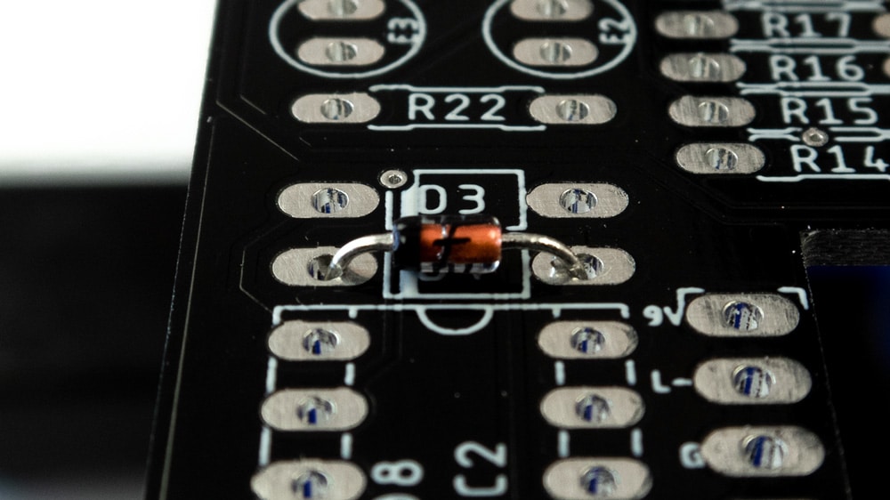
Footprint of the D4 diode, with a bold stripe to show where to put the cathode.
Once the diode D4 is on its location with the black stripe on the left.
place a diode on the pcb
Once we have the value, we have to be carefgul, there is direction on the diode and it is very important! the ring drawn on the diode shows the cathode, the “-“, it is also drawn on the PCB. Then you have to mount it with the stripes of diode and of the PCB on the same side.
In pedals, we find diodes for various fucntions :
Clipping! Diodes clip the signal which creates that distortion we love so much. See the article.
Power supply protection, current can only go through the diode in one direction, from the anode to the cathode. Thus, the current enters through the side without the ring to the side with it. By cleverly using diodes, we can block reversed power supply connection from destroying the device. We just have to take care that the diode doesn’t burn due to a too intense voltage. So PLEASE when it’s written”9V DC” on the pedal, don’t plug a 18V power supply if the manufacturer doesn’t allow it. Or there will be smoke!
transistors
Freshly cut BC549 transistors! Please notice that one face is flat, with its value written and the other is round.
identify transistors
To begin with, there’s a lot more room on a transistor to write things! On the flat face is written the value (Most of time starts with 2N or BC). The round face is used a mark. This curves are also drawn on the PCB to identify where to put which side.
Transitors are made of 3 electrodes. Regarding the transistor itself, they have different functions and different connections. (If you want to learn more, search “YOUR TRANSISTOR REF” then “PINOUT”). But in our case, there is no need to do it!
mount a transistor on a pcb
Transistors in the right position. Round face over the curved drawing.
The right one is reversed!
Plug the transistor, fold the legs and solder, once more, that’s all you have to do! In our circuits, most of the time we use transistors to amplify a signal or to adapt impedances. Look the buffer from this article. And we’ll talk about it later in future articles.
On the left the transistor, and on the right its schematic drawing. Very useful example to understand the pinout and how to mount it.
intergrated circuits (op-amps and others)
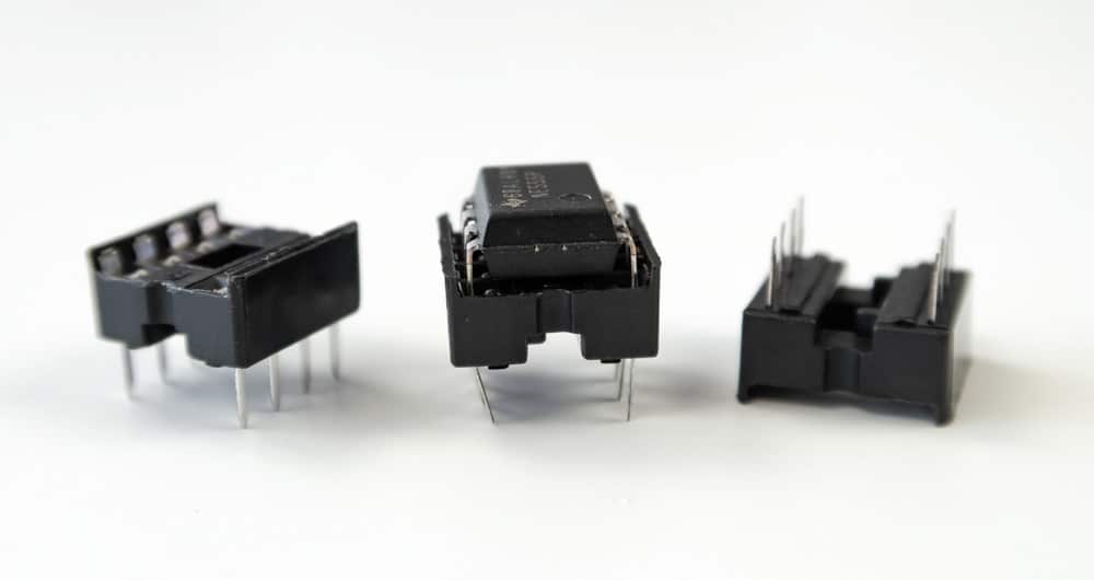
A NE555 with its DIP8 socket. Note that there is a dot on the chipset and a notch on the socket. Both are on the same size.
We can read its value directly on the top of the IC. NE555, TL072 etc… Remember to solder the socket first, then plug the chipset on it.
There is a notch drawn on the DIP8 socket location. It is the same as the one on the DIP8 . Une Once soldered, just had the IC with the dot on the same side.
Warning, IC need to be placed with a specific direction! Each leg is very important and does rigorously different thing! So make sure to mount the socket first. Whether a stripe or a dot for the ICs, and a notch for the socket and the PCB.
various ways to represent a chipset on a schematic. On the left, a TC1044 which is a power supply chip, drawn rawly with its 8 legs In the middle, we have an op-amp, another type of IC we use a lot. It’s easier to draw in various smaller parts on the schematic. On the right is a part of an op-amp, these are the 2 legs connected to the power supply.
Op-amps are very nice amplifierswith which we can do a lot of things! High quality filters, give gain to the saturation stage, etc… It’s a primordial component to all of our designs! We’ll talk about it more in depth later too.
trimpots
The trimpots!
identify the trimpots
Trimpots are nothing more that miniature potentiometer on PCB ! They allow us to offer thin adjustments and to add settings.
On the pic, the left trimpot is shown in top view. There is a screwdriver print with 2 half-circles. It shows us the cursor of the trimpot. Here it is halfway of its total range.
The right one shows the value indication. It’s quite like ceramic capacitors, P103 for 103. 103 being 10 x 10^3 or 10kOhms. Yes trimpots unit is “Ohms” just like resistors, simply because they are variable resistors!
mount a trimpot on a pcb
How to place a trimpot on a PCB
Once placed, as usual, fold the legs outwards,flip, and solder !
2 terminal blocks. Plug your component in the sockets and tighten the screws so it doesn’t move!
We’re going to see them a lot with FX teacher ! On one hand it is soldered on the PCB thanks to its legs. On the other, we connect the new component we want thanks to the hubs. To do so just screw it to connect it to the circuit!
It’s great tool for learning and audio discovery that we cherish at Anasounds!
Une fois sur PCB
Of course, be careful to place it in the right direction. So you can easily access the hubs to put component legs. We left some free room around them to manipulate and let the components breath.
did you like this entry?
Do you want us to do more? Support this project and subscribe now!
Get ready ! In this article you will discover a lot of theory and practical advice about welding. Then, we will also mention how to solder some specials and tricky components! We will also take a look at the needed equipment to start welding in the perfect condition.
hand soldering tools
The perfect soldering bench !
In fact, you can start quickly and affordably with a few gear. So we go, still in a DIY spirit, we’ve separate the list into 3 sections. The essentials, the comforts and those for the pros. You will soon realize that the more you prototype and the more you will want to equip yourself. This make the experience so much funny and enjoyable!
essentials
Your kit / prototype, with the components to place on your PCB.
A soldering iron. There are all very different and it can be hard to identify the one you are looking for. For small budgets we offer this iron from the Japanese brand, Goot. It will be very useful and efficient for some kits from time to time.
Tin! There are 2 major family of tin. The ones with 60% tin and 40% lead and the others with 95%-99% of tin + copper and/or silver. The first one is the easiest to weld but the worst for the environment. If you have a really bad iron, go for it (but, I never suggested that …). Otherwise with a good iron like the ones we propose, use unleaded tin !
Cutting pliers! You’ll be able to make it with a big electrician’s pliers. But you may twist your beautiful welds by going a bit too wide! A small and dedicated plier, with the good shape will allow you to preserve your job and make it much easier.
What to strip a cable. It can be a cutter, a lighter, your teeth, all the tools found by MacGyver … Or simply, a wire stripper.
A table of course! Be careful the tin provided create small splashes of flux. It stains and sticks …
A tip cleaner, and not a wet sponge! No more temperature shocks, we clean our iron tip in a metal sponge to get this perfect result.
The third hand! This tool helps you to hold a component, some cables, a PCB … This is what we all dream about, a 3rd hand !
A rotating PCB holder. The holy Grail for a few bucks. The PCB is held in a vice and can be turned on itself to place components and weld. On the other hand at this price, the tool is quite strong. For an everyday use we have some much more advanced equipment. Like the one we use in our productions. But for some kits, you can go for it!
A desoldering pump! And yes stupid things happen quickly. With this one you can easily empty a pad, filled of unwanted tin!
Some tin plated desoldering wick! By heating it up on a pad it will suck the tin by capillarity. It is much more efficient than the pump if you want to remove a component, but it requires some technique. The pump is still super nice to empty a pad when you start.
A tip refresher. This is optional for those who use lead but for those with unleaded tin it becomes almost vital! We dip the hot tip in this paste to refurbish it. At the office, we use it every day. Several times a day…
A soldering station! This is more for those who want to play the game seriously! The Goot brand also offers stations that we use every day to solder our PCBs by hand. The result is just bluffing! We weld much faster and much better. The tip last several months. While it is used almost 8 hours a day, 5 days a week. On the small irons, the tip is wicked part and you have to replace it quite often. It is also the most important part for a good quality of solder joint.
A fume extractor. When we just do a kit from time to time, we can open the windows and then, we avoid putting the nose in the smoke. This could be fine for a short time period, and still can be dangerous. Because it is true that it is strongly inadvisable to inhale these fumes which are very irritating but fortunately not carcinogenic.
A tin reel dispenser, a nice small luxury. We pull the wire and he will come by itself to your joint. You will see when you have made many projects, you will dream about it!
soldering theory
Game over
If you want you can skip the theory and go straight to the practice. But if you are curious, there is plenty to learn here.
what is a solder joint?
The component leg is made of copper and the manufacturer has added a tinning (tin covering the copper). It’s the same for the PAD, the hole on the PCB which hosts this component. Over time, oxygen and moisture in the air attack this coating and oxidize it! I.e. a layer of another composition is added on the surface. And there, no luck, if we want our signal goes from the leg component to the pad, with such insulation it’s going to be complicated! Then anyway, the solder will not hold on for a long time.
PCB’s pads oxidation over the time
So we have a quick fix, the FLUX. It is a chemical product that in our case, is integrated into the tin wire. He will strip (de-oxidize) the pads to make them clean and welcoming for the tin. To work well, it is necessary to pre-heat the surfaces between 130 and 150°C in order to activate the flux and to be able to clean the surface.
The 4 stages of welding are represented here with the temperature of the tin as a function of time. First we put the iron, we add the tin, then we remove the tin and finally we remove the iron.
the different alloys
Once the card has preheated and the flux is acting, we need to take care of our alloy! Either tin + lead for hobbyists or tin + copper for those who follow the RoHs ecological standard! The first alloy has a melting temperature close to 183°C and the second requires at least 227°C! We understand better why the lead-free solder is more difficult! It requires more heat. Then, the chemical agents are different and they attack more the tip of the soldering iron. Then, we must learn how to maintain it.
let’s make our first solder joint!
The perfect solder joint exists!
The 4 steps:
Put the iron to preheat the solder joint
Add some tin gradually to prevent a temperature shock
Reset tin when the gasket is filled with tin
Remove the iron along the component leg to create a beautiful, perfect dome
That sounds very easy like that though it takes a little practice to get a good result.
the different solder joint
The different results you can get by welding. If you do not have a beautiful dome as on the first example, it is that you are missing welding and it is necessary to do it again.
In analog electronics, poor welding can lead to multiple problems. And they can sometimes be difficult to detect! The worst part of all this is that a bad solder is getting worse over time. So it’ll be worse and worse and hard to detect! So take the time to make beautiful welds and be sure of the result. We will have a PCB that can last more than a decade!
This should keep in time! The cutting of the legs is just above the welding dome.
You managed to make a beautiful dome welding as in this example? Did tin came through the PCB to create a 2nd dome?
When the weld is perfectly made, the tin comes out of the pad component side. It is well to the left and right not good enough.
the different leads cutting
The cutting of the legs of the components is essential. If left as is, it may be that the legs are touching each other, creating short circuits! So we will take our cutter and come cut the exceeding part of the lead at the top level of the “volcano” created by tin. Be careful not to cut too short or too long! In the first case you risk to damage the solder joint, which would age prematurely. In the second case, it may damage the cables around, or create false contacts with the box or other areas of the PCB.
equipment maintenance
The 3 essential tools to have a healthy iron!
Obviously the welding is better with a quality material and in good condition. It had to happen to you to try to weld with a carbonized tip, then the tin does not catch and it’s hell!
my morning routine
Important gestures to keep a soldering iron in good health!
When I start the iron, I find it very useful to “wake it up”. Once it’s hot, I plunge the iron into the tip renovator to restore its youthful glow!
Then I put a lot of tin on the iron until a ball is formed. Then, I rub the tip on the tip cleaner to strip it. I am finally ready to weld.
When welding unleaded at a station, avoid putting it thoroughly, thinking that it will work better! Personally I like working at a maximum of 380 ° C.
When I stop welding for a few minutes, I lower the temperature of the iron, or even turn it off.
Every 5 to 10 welds, I rub the tip on its cleaner to turn tin dragging over and no longer flows.
Every 3h I like to put a little bit of tip renovator. Then, it goes again… fresher!
When the tip is too carbonized or it starts to darken every 10min, it is useless to fight. It is impossible to recover it in a sustainable way, so you have to get rid of it and replace it!
In the evening before switching off, we clean and then renovate the tip. The next morning it is like new!
for specific components
Come on, the last step to succeed all your projects!
potentiometers and switches
All tutorial video to weld switch and knob on PCBs.
You really lucky, at first we decided to wire them by hand!
Big amount of wires right?
Then finally, we had some good heart. We thought it would be nice if you come back to see us the next time we release a kit! So we found a supplier who has knobs and switches that are soldered directly on the PCB!
A knob and a switch mounted. We can notice their footprint on the PCB.
To solder them, there’s nothing simpler!
You return the board
You put the switch or the pot
On the same side you put a little tin on the metal reinforcements on the sides of the component so that it holds all alone.
Then you flip it again
You cut all the legs cleanly by being careful not to burn a component around with your iron
You redo the welding you had done on the other side at first so that it is perfect!
The rendering on the component side of the PCB, after welding a knob and a switch
the led
Usually a LED is in a through hole format, which has the same legs as an electrolytic capacitor. For the purposes of our design we have been using for some years a slightly more recent LED technology. It is white and sends more lumens than the previous one but it consumes a lot of current! The only format that exists for this LED is in SMD for Surface Mounted Devices. It requires a particular welding technique and a couple of equipment. So we have a method to share with you which save time and avoid having lots of equipment!
A video to show you how to solder the LED SMD
The different steps :
Put some tin on the positive leg (the one on the top of the PCB)
With needle-nose pliers, preferably angled, catches the SMD LED.
Attention LED has a polarity. You can identify the +, it is the side where there is a setback on the top.
Here the “+” is on the right. There are several soldering pins, all those on the left that are visible are the “-“. While those that are not visible to the right must connect to the “+”.
In one hand you hold the LED and in the other you come back to heat your tin pie.
You put the “+” side on the tin. Too bad for the quality of welding the goal is only to focus on the location of the LED.
You remove the iron.
Once well cooled you pass on the “-” and you make a nice weld by catching the 3 legs to make a nice pie nice. Enjoy! It’s the only time it will happen!
Once fully cooled you come back on the “+” and you remake us a nice weld.
Done!
pins
You will notice at the bottom of your PCB that there are 2 places to come weld pins. They will maintain your footswitch and communicate between the main board and the 3PDT.Again it is an “optimized” method that avoids wiring but it generates a bit of welding technique.
A small vid of the technique
For this technique we will weld a pin approximately then we will return to better weld.
So you have to hold your pins on one side and weld on the other. Beware if your finger is below you’ll burn you by conduction. It stings! We must therefore put it on the farthest one at the opposite of the one you are soldering.
Once this pine is welded you can do the others cleanly.
Then you come back on the first pin to make it better.
In this article you will learn how to wire the jacks of a pedal and all the! And yes, unfortunately, we don’t hold everything on the PCB…. We will also teach you a lot of welding and wiring techniques. It is nevertheless essential to keep the adventure ! And then, when you have to wire, you also think about the ground loop…. Come on, let’s go!
required tools
All the tools you need to succeed with your wiring!
A soldering iron, for small budgets we offer this iron from the Japanese brand Goot which will be very useful for some kits from time to time.
Tin! Tin! There is tin with 60% tin and 40% lead, which is easier to solder but very bad for the environment. If your iron is truly bad, go on over there (but it breaks my heart). Otherwise with a good iron like the ones we propose, use unleaded tin.
A cutting pliers! A small dedicated clamp that perfectly fits the shape of the component legs. All we have to do is to cut it off!
Something to strip a cable. It could be a cutter, a lighter, your teeth, all the tools MacGyver has found…. Or simply, a stripping pliers.
A table, or a bench! Be careful the tin supplied creates small flux splashes. It stains and sticks….
A tip cleaner, to clean your iron with a metal sponge that does the job perfectly.
A third hand! Still a very practical tool at the end.
A tip refresher. To have an iron that is constantly at its best!
A nose pliers to bend your wires properly. Otherwise it also works with your fingers…
In a pedal you can find solid or stranded wire. This means that your signal goes through this conductor via one or several copper conduits. In high-frequency applications, the stranded wire is always preferred to avoid an edge effect that would produce losses. In this case, in the audio world, this effect is very strongly negligible since the frequency does not exceed 20kHz. So we simply have a lot of possibilities regarding our wiring wires. Having worked with both types, I can guarantee you that it is more pleasant to work with rigid wire, so solid wire. It folds, there is no need to tinplate it…
Solid wire
Stranded wire
In terms of length, you don’t need to buy 30m reels to make a few pedals! All you need is a few wires from 7 to 10cm to connect the different components. It is especially important to pay attention to the diameter of your cable to allow enough signal to pass through and avoid overheating. (This is especially true for your power connectors, if they consume a lot) We rely on AWG22 in to be very, very wide!
color code
By repeatedly wiring boards we have defined our own color code so that we can easily find our way through them. You can choose to adopt it or not, it’s up to you! In any case, it is thoughtful to quickly identify a defect and then control the production quality of the device.
The white is associated to the input signal, it is the one that enters the board. It is soldered to the board on the pad marked “I” for IN.
Green is the color linked to the output, it is the signal that comes out of the board. It is connected to the pad labeled “O” for OUT.
The red is the positive terminal of the 9V power supply of the board. It is connected to the pad marked “9V”.
And the black for the ground, are to be welded on the pads “GND, G, G, G1 and G2” for GROUND.
prepare your cables
The 4 wires that leave the card allow the signal to be transmitted to the jacks and to supply the card.
You must first equip yourself with a cutting pliers in order to cut them to the right length. Then, the cable end must be stripped on both sides. Then, bend the conductive part at 90°.
How to strip and bend cables
You have several options for stripping your cable. We show you here with a manual stripping pliers that we propose, and with an automatic stripping pliers. You understand that when you prepare dozens of pedals at the same time, at the rate of 5 wires per card, you like to have the luxury of an automatic stripper!
We will now solder them on the PCB. Be careful not to melt the wire jacket! Plastic can contaminate your joint and deteriorate its quality and durability.
A video to show you how to solder the cables you just prepared on your card.
audio jacks
anatomy of a jack
A jack seen from the bottom. We notice that it is not a perfect square, there is a small flat spot on the upper right that indicates where the ground is. Then, we see on the left a tab which is the one that fits with the tip of the jack. So we weld our signal on the left.
In a female jack, there are 3 pins that interest us: the Tip, the Ring and the Sleeve. Hence the name, jack TRS….
The sleeve corresponds to the ground, our reference point.
The Tip is the pin that carries the signal when you are in mono.
And finally, the Ring which in the stereo case, carries the other audio channel.
On the left there is the male jack and on the right there is a diagram of a female jack.
the ground
When you forget to connect the ground, you just hear a big BZZZZEEEUWWEHHEUUUU. That is, an angry amp. And yes, you already experienced it when one of your cables died.
The different symbols that represent the ground on a diagram
It is however the basis of an electronic circuit, the value of a signal depends on its reference! If you have not connected the ground from one circuit to another, they will have trouble to communicate because their reference levels are different!
Anatomy of the mono jack cable we use for our patches! At the top is the well-known Tip that carries the useful signal. Then we surround it with insulation and a beautiful ground braid, the metal part just below.
In the case of jacks, the ground is also often used to shield our signal. The central core must be completely surrounded by the level 0, the ground that will allow the parasites to be captured and filtered. Like a shell that fights against disturbing waves!
solder a jack
Here’s how to easily solder a wire to a jack
With the 3rd hand, I clamp the inside of the jack to hold it vertically
I insert my wires into the legs of the jack from the inside to the outside
I preheat the jack tab and the wire with one or two drops of tin
When I see that the tin’s color has changed and that it is very bright, I can put the rest of the tin on to finish the soldering properly.
I remove the tin and then the iron.
I make sure that my wire does not start to oscillate. If so, I can hold it gently on the other side without moving. Indeed, it is absolutely necessary that it remains immobile to obtain a perfect weld.
I’m cutting off the excess leg of the wire we just soldered.
DC jacks
pedal power supply
Without energy, an electronic circuit can never work!
This is often the most stupid mistake but at the same time the easiest to detect.
The power connector on your pedal.
The power jack is already attached to the pedal enclosure. You will notice that there is a long leg and a short leg. The long one is for the +9V and the short one is for the ground.
Interesting little aside on the power supplies. A power supply imposes a voltage. While it is the circuit that sets the current consumption. Thus, a 9V pedal requires a 9V power supply. If the pedal consumes 20mA and the power supply can supply 500mA everything is fine! There will be 480mA left available to power something else. In any case, only 20mA will be consumed.
solder your DC jack
How to properly wire your power jack once your board is mounted
Using your nose pliers, place the red wire connected to your board in the long leg. Then do the same with the black wire in the shortest leg.
It may seem a little complicated to handle the soldering iron in a small space. But with a little practice it goes very well. Also be careful with your iron to be “vertical” enough to avoid burning a capacitor or any other components.
The poor trash! Once the card is ruined, it is difficult to identify the breakdown…. What if there is a way to avoid that?
Since 2013, I have been doing a lot of prototypes! And I am sharing this experience with collaborators, trainees, musicians… Unfortunately, I see the same mistakes every time! The most frequent one for my Padawans…. They want to rush! As soon as we receive the PCB, they get excited and go for it! 2h later they plug it in, play some chords and….. Well, it doesn’t work!
the principle
As Homer do, check your solderings step by step!
The methodology has 3 goals :
Learn how the circuits work
Mount and check each blocs one by one
Avoid unrecoverable mistakes or at least identify and anticipate them easily!
To do so, our team breaks down how they work. Then we’re going to explain step by step what you need to measure and what you need to see. If a value doesn’t correspond, you’ll know where it comes from. Then you can easily describe you problem to the FX Teacher community, or even debugging by yourself. Just read the schematic again and surf through the internet with the terms related to your problem.
in specific terms
You’ll have to build a tester. It will allow you to inject and listen the signal on various points of your board signal. It also allows you to easily supply your board.
For each kit our team will provide you a complete article describing everything you need to know about mounting and measurement.
Voltage and current measures will give you the perfect working point of the circuit. Then, thanks to the schematic, if a voltage is not good, you’ll quickly know if the IC is upside down for example, or if the transistor is badly welded, if a cable is broken, etc…
Audacity measures allow you to record your signal bloc by bloc and analyze its evolution. Then you’ll learn a lot of things on the effect you’re building. Also you’ll understand the impact of the settings of the trimpots and pots. Moreover, if your buffer is sucking your tone, you’ll be able to realize if you mixed up component values somewhere.
Assemble the tester
The kit to make the tester is available on our store
To build your FX Teacher tester, here are the tools you’ll need :
The tools you need to buid your tester in the best conditions.
A soldering iron. We have this good craftmanship 30W soldering iron from the brand Goot
Tin. Leadfree of course ! Environmental-friendly !
Without energy, the circuit will never work! It is moreover the most ridiculous mistake but also the easier to spot. “Erm… It doesn’t work!”, “You didn’t plug the power supply you piece of cake!”
Well you understood well, we’re going to start with the power supply bloc for each of our kits! By the way, this jack has 2 duties. The first one is to provide the circuit with energy for any 9V power supply. The second one is to easily allow you measuring your current consumption. It is made so you don’t have to solder and desolder cables, thanks to its claws. Maybe it’s not very striking. But believe me, it’s a huge gain of time!
How to assemble it
We’re gonna start by soldering the female jack connector, in which you plug you power supply. As electrolytic capacitor work, the long leg is (+) and the short one is (-). By convention we’re gonna connect the red cable to (+) and the black one to (-). Cables are between 8 and 10cm. No need to heat a lot, it is easily and quickly soldered. Moreover the pin inserts are made of plastic, so we better not damage them.
DC jack with its 2 cables
Now we’re going to cut 4 pieces of heat shrink tube that we’re going to put on the jack side.
Then add the heat shrink
We continue by clamping the other side of the cable with the crocodile clips
How to clench the crocodile clip
Here we’re going to heat things up! The contact surface is wider, do not hesitate to heat and wait a bit to pour the tin. You’ll see, once the clip is at the good temperature, the tin will spread. Thus using a third hand holder is a good idea to avoid burning your table.
Everything is in place ! Now we just have to take care of the heat shrink
We wait till it’s cold. Then we overlay the weldings with the heat shrink tube pieces. Finally, we have to heat with the upper part of the soldering iron (the opposite part of the tip) or a lighter. If you have a hot air station it’s even better!
The whole DC jack tester ! Wasn’t to hard I hope ?
But wait! You have a cable and 2 crocodile clips remaining! Solder one crocodile clip on one side Wait till it’s cold Add 2 pieces of heat shrink tube on the side you just soldered. Solder the other crocodile clip Finish by shrinking the tubes.
Once this part of the tester is done !
We’re going to use this clip to measure currents with desoldering everything!
How to use it
The power supply bloc is the first one we’re going to assemble! To do so, follow the instructions on your tutorial and you should have something similar :
Your PCB with the power supply bloc and the 9V and GND cables only
You can then solder the black cable and the red one on your board. They will always be mounted on your board from start to finish.
Now plug your power supply for effect pedals on your kit. Use the clips to connect the red clip to the red cable and conversely. There’s very little risk to make a mistake here!
The DC jack tester connected on one side to the PCB with the red and black cables. And on the other side with a 9V pedal power supply.
You know what? It’s done! Your circuit is power supplied. Now you can to the multimeter section to understand how to read voltages and currents. You’ll then be able to compare your findings with the given table provided in your kit.
audio jacks
what does it serve
The main goal is to be able to easily listen with a guitar and an amp or with a sound card, the outcome! So we’re going to to plug those jacks on each bloc of our kit and analyze its impact on the signal.
How to assemble it
Let’s begin by identifying the functional anatomy of a stereo female jack :
First we have to solder a white cable to the tip connector of the jack. Then a black one the ground connector. Just repeat for the output jack with a green cable. Cable lenght, approximately 10cm.
First soldering step achieved! We set the flat spot on top just so we get a mark for pictures. It will soon be .
Cut 2 small pieces of heat shrink tube and put them on the jack side.
Heat the heat shrink on the jack side. Wait till it’s cold and add the 2 left pieces.
Now solder the other crocodile clip. Be careful to tighlty clamp the clip on the wire with the nose plier
Time to heat things up again! The metallic surface is wide, so you have to heat the clip, and when it’s hot enough the tin will start spreading easily and it will be shiny.
Once the crocodile clips are clenched on the cables
With the upper part of your soldering iron (the lowest temperature-wise) or a lighter, shrink the tubes on the exposed metallic parts.
Here it is! It’s done!
Just do the same for the output jack tester with the green cable instead of the white one.
The whole output jack tester! Let’s use it now.
How to use
As you noticed it, they’re jacks. So you can easily plug an input and ouptut jack, and listen to the result.
A not very useful loop! This is just to show you that grounds are always connected together (black cables). The input signal goes in the white one and goes out with the green.
When you’re board will be finished, you should have one white cable, one green, and two black ones. Just catch them with the crocodile clips and you can appreciate the outcome. Even without a housing!
Use the clips to clench on the cables ! You can easily test the whole card!
The FX Teacher methodology is the same idea. When you’re first bloc is finished, we exactly tell you where to place your wire to inject your guitar signal and analyze the bloc impact on your computer.
A finished card with all the testers connected. We’re ready to listen !
So it would be convenient and easier for you not to break your tester or your PCB in the long run, we decided to solder cables on those points.
When you’re testing a bloc, solder a white cable directly on the component lead. Then do the same with the green cable!
Once the cables are soldered, you just have to connect them with your clips.
Only the power supply and the input block are soldered. We can check this part of the PCB before going further!
Now, to analyze your signal you must plug your sound card! Nothing special, plug the output jack of your sound card to the input of your PCB. Then the PCB output jack to the sound card input.
Et en schéma ça donne ça ! Tu branches la sortie de la carte son sur l’entrée de ton PCB, et tu ré-injectes ce qui en sort dans ta carte son !
The dedicated tester to the method, to build on your own!
A multimeter, you can find this one and that one on our website. You need a simple and efficient one.
A computer with Audacity on it. People talk crap about this software, but you have no idea what you can do with it
Brain juice! So don’t forget to bring it fresh!
A killer community! If you need help leave comments and we would be glad to answer. A dedicated forum to FX Teacher is taking shape!
use a multimeter
I know you’re going to love it! When protoyping, the multimeter is a must have… So we’re going to see together how do to the different measurements so you can easily compare your circuit to the reference table.
voltmeter
theory
This is the easiest unit to measure, just plug yourself in parallel connection! Which means that the circuit works normally and that the voltmeter comes “from above” to check the signal. So you get a measurement in Volts, V. Actually it’s a potential difference. A potential which is different on the voltmeter pins. That means that whenever you’re making a voltage measurement, to get one pin on the circuit where you want to make your measure, and the other on ground!
connection
Plug the “+” on V for Volts and the “-” on COM. Then switch the mode to V DC for a continuous signal. Be careful not to choose V AC for an altenate signal which is a V with a wave on top.
Use the clip to connect the “-” to ground. Now just trigger the spot you want to measure with the red tip!
amperemeter
theory
Compared to voltages, currents are measured in serial connection! Indeed, you have to be able to know the amount of electrons rushing into and out the circuit. To do so, we’ll take the main entrance, the red cable! Then your multimeter will do the job counting the electrons per second!
Put your multimeter to Ampère mode mA. If your mutlimeter has a mA mode, chose it. It will be more precise than A. Then connect the cable to the adequat socket.
connection
The two-headed crocodile clip will be useful here, connect it between the red cable off your PCB, to the red clip of your DC jack tester.
photo sur la carte
As we told you, the ampermeter is plugged in serial! So you must use the small cable with the 2 crocodile clips. Then the power supply current goes into the amperemeter and then goes to the card. And finally goes back to the power supplywith the black cable. (Electrons actually go back the root!)
continuity
The continuity test should help solve a lot of your problems! It’s about resistivity measurement. But here, the multimeter will bleep when the the resistor value is 0. Which means that both potentials are on the same point! There are only 2 situations in which this potentials are 0. First option is when the developper purposely link to areas together on the PCB. The second option is when you do bad welding that creates a bridge between 2 pads!
To measure continuity, we actually measure the resistance. Go the Ohm caliber and choose the option so the multimeter “bips” when there is a continuity.
So we often use this method to check every area of the board by bleeping risky areas. It allow us to know where the issue comes from. You build your board bloc by bloc, so it will be super fast to go through the PCB! However, this methodology only works if you know how to read a schematic and a PCB on Eagle. You’re not obliged to use it on our kits to debug them, but it’s better to learn it at least.
photo de la carte en test avec un pont et la r à 0. Meme sans le pont.
Power supply load
We’re often taught at school a perfect power supply gives a nice 9v, and that’s it! That’s completely false. The power supply always has an output impedance, depending on design and performance. It’s only a few hundreds mOhms but you’ll see it affeccts its performances.
E is our power supply, Ris its internal resistance and Rch the load resistance.
Without a doubt you heard about the Ohm’s law. U = R* I. Voltage = resistance * current. So if you draw 1A in the circuit, with an output impedance of 0.1Ohms, you’ll lose 0.1V. Actually it’s no big deal in this situation. But sometimes other impedances add themselves to the power supply signal path. So you might find yourself at the end of your path with a few tens of Ohms! On the other hand, we lose a lot of voltage if the current is high. You’re lucky, on never top 200mA in effect pedals with semiconductor. Just remember that with 10Ohms, it is 2V of loss!
Thus by building your board bloc by bloc, you’re going to make measurements of a power supply which is not sending any current! So we’re going to build step by step and then come back to check everything once in load. You’ll see that some voltages might change, others might not. So it’s a double check for mistakes like ripping a cable, or creating a bridge over pads.
Here’s an example, the voltage reading of the input block of the Ego Driver! We give you the interesting points to make your measurements and check your card correctly works .
sound card measurements
The sound card is a wonderful tool that is not only useful for recording demos! We’re going to discover what we can do with a simple but efficient software like Audacity.
Bases of signal processing
Before getting into manipulations, some reminders on signal processing. Or teaching for some of you. I’d advice you to go check the subject in depth if you’re interested because we’re going to approach it quickly! And it is wonderful to me, as a musician.
signal amplitude
You saw previously that we can measure the voltage of a signal in Volts, thanks to a multimeter. In a sound card your signal can’t top a maximal value depending on the model. Let’s imagine 5V. If you send a signal bigger than 5V, it’s going to clip, adding a lot of harmonics that don’t sound great.
Thus the dBFS unit was born, for decibel full scale. If you send a 5V signal in this sound card, it is 0 dBFS. If you send a 2.5V signal, it is -3dBFS. While dividing by 2 an amplitude, is equivalent to losing 3dBs.
So it is interesting for recordings to work between -6dBFS and -3 dBFS. But if you’re recording an OD and you crank up the gain, you might go to +9 to +15dB. You would exceed the 0dBFS so there would be saturation. And then we come back to the clipping problem… A clipping sound card does not sound as good as a clipping OD!
Therefore, we chose -12dBFS to optimize this gap that might get analyzed. Or we chose -3DBFS and we start recording once the pedal volume control is set.
snr
SNR Representation. In yellow you, a signal going up to 0dBFS and in red is the noise around -80dBFS or 80dB SNR !
Why don’t we simply choose -20dBFS? Because of the SNR! Signal Noise Ratio. The noise floor of system is often between -60 and -100dBFS. If you”re signal is around -10dBFS, your SNR is 100-10 = 90 dB in the best case. You must keep an excellent SNR if you want good measurements. So we can’t send a -20dBFS signal if the noise floor is -60dBFS. You might lose a lot of useful informations harmonic-wise!
time signal
To represent these analysies, you have a temporal and frequential representation of your signal. Time signal is exactly what you would be measuring with your multimeter if it was precise and fast enough. Then you would note step by step its time evolution. So this measure is purely physical.
the tff
In contrast the TFF is a signal we invented to analyze the signal in a better way. Here’s the formula, you might like it :
What you must understand is that the TFF is a signal calculated from the time signal. And we don’t show the amplitude as a function of time, but as a function of its frequency!
Common stimulis
The sinus. It is the easiest one to use. A pure note made with one and only one frequency. For example, the 60 cycle you have on your wall socket is a sinus. We often use a sinus to observe the saturation of an OD. If the signal goes into saturation, known harmonics appear (100, 150, 200Hz…).
Sinus in time. The signal is perfectly balanced.
TFF of 997Hz sinus. The function is Welch, which allows to see its bending. A Blackman-Harris would be nicely straight. A rectangular function would be spreading over all the frequencies
White noise. It’s a signal containing all the frequencies of the audible spectrum randomly generated. That’s what you’re hearing when your radio has no signal! We often use it to check the efficiency of a filter.
Temporal white noise. We can clearly see that all the points are randomly generated
White noise TFF. All the frequencies are shown and their amplitude vary of at most 0.5dB which is almost nothing
Sweep. We’re going to create a succession of sinus whose frequency is gooing to change through time. For example, we use a sweep from 20Hz to 20kHz to represent the audible spectrum. It is one of the stimuli I use the most because I can learn almost everything I need about my filter!
Only the start of the sweep, shown in temporal. Note the sinusoid oscillate faster and faster. Which shows that the frequency increases.
the spectrogram
To do a TFF, you choose a sample of your time signal and you calculate it frequential content. Now imagine a filter that changes with time! To analyze this kind of signla, we invented the spectrogram! The software is going to make a TFF on a lot of samples of your signal in real time, then you’ll have a 3D representation of your signal. The signal evolves in time on the X axis, frequencies are shown on the Y axis and finally the color shows on Z axis the power in the frequencies.
Spectrogram of a frequency sweep. Note the white areas are rich in energy, whereas the blue is low . We start very low in frequency and we end up to 20kHz. It shows the evolution of our sweep.
We mostly use it to see how the filter act according to time on different riffs or to adjust precisely a filter. This is often what you see when scientists analyze singers vocal chords.
What you most know about Audacity
So here we go to do a visit of the Audacity software. I will show you everything you must know to follow our tutorials.
Set the audio peripherials
How to select the audio device on Audacity
Before starting your project you must check that you’re sound card is configured the right way. To do so, check you chosed it for input and output. And not the intern device of your computer
How to select the sampling frequency
No need to choose 96kHz for sampling. Any card working with 44.1kHz, 24 bits will do. Afterward if your sound card allows it, you can go higher with this parameter.
generate signals
For a sinus : go to Generate -> Tone. Then choose the frequency you want. We set the amplitude around 0.2, it is more than enough knowing that a guitar signal amplitude. About time, it’s up to you, 1min in our case is good.
Control panel to generate a sinus
For a white noise : Generate -> Noise. Simply choose “white”, amplitude 0.2 and the time you need. There are different noise colors, you can check them out.
Control panel of noises
For a sweep : Generate -> Chirp or “Gazouilli”. We often select sinusoid, amplitude 0.2 from start to end. Start frequency : 20Hz, end : 20kHz. Linear interpolation and 1min time.
Sweep control panel
Record a signal, mute, solo
Once your signal is generated, you ‘ll have to send it to your circuit board and record at the same time. So you must change the software parameters to be able to read and record at the same time.
Once you’re done, the first recording is simple. Plug everything in and hit the red button to record. If everything’s fine, it’s recording, then you stop when you want.
Be careful when tracks get piled up. Keep in mind to hit the SOLO button to avoid sending multiple signals at the same time!
The top track is soloed, the bottom one is muted.
set sound card and signal level
We’re going to use the Vu meter at the top of the window for this step. Before measuring, you must calibrate your sound card. Plug in a jack between the input and the output of your sound card to make a bypass. Send a long 1kHz sinus, for a few minutes, with an amplitude of -12dBfs and record at the same.
First I generate a sinus as usual. Then I go to Effects -> Amplify. Then I set le top around -12dB. And that’s it!
No adjust the input potentiometer of your sound card so the input level is exactly the same as the output one.
Imprim ecran -12dB output et input
do a tff
Generate a signal or use a recording. Then go to Analyze -> Draw spectrum
A 997Hz pur sinusoid with a rectangular window
The same pur sinusoid with a Welch window
About windowing
The window will affect your analyze. You must have some theorical knowledges to set it nicely. We know a sinus a only one ray. So we’re going to be more likely to take the right window. We will need to adapt ourselves because no windowing fits every need! In our case, Blackman-Harris was more strict but so much more precise that we barely see the ray at 997Hz.
The next step is the point number. The more you have points, the it is defined! But sometimes we are more likely to use less points to get a smooth result which is necessary sometimes.
A sweep with 8192 points and a Blackman-Harris windowing
Same signal, same windowing but with 32768 points
We have much more details that does not confirm theory and are useless for our study.
Last point but not least, the scale on the frequency axis. It can be linear, which means the gap between 100 and 200Hz is the same as between 200Hz and 300Hz. It can also be logarithmic, which is actually how our ears work. Here the gap between 100 and 200Hz is wider than between 200Hz and 300Hz. It’s a little bit more complex than that so here’s the formula if you want to learn more.
A signal full of mids displayed with a linear scale
The same signal but displayed with a logarithmic scale
As you can see, on the right we’ll have much more informations on what goes around 1kHz. And this is between 100Hz and 6kHz that most of our guitar signal is!
Display a spectrogram
Here, nothing’s easier! Go to the signal you want to analyze. Regarding the present case, it is shown in a temporal format. Clic on the small arrow on the top right corner. A lot of options apppear, and sepctrogram is part of them!
How to display a spectrogram
Common mistakes
Ask us your questions! As they come we’ll take time to reference them here.
When you’re on stage, the true bypass simply turns your pedal on and off. Quite useful for a system!
So we’ll see how a true bypass works, its design, the different technologies and, how it is installed!
If you are reading this article because you are making a FX teacher kit, you can go directly to the realization step and then come back to the theory another time. But hey, you might miss something! For the kit with 3PDT click here. For the kit with relays click here.
what we expect from a true bypass
That’s it !
When the pedal is bypassed, it means that you don’t go through the effect. To achieve this, the guitar signal passes through the input jack and then enters the switch, then the signal is routed directly to the output jack and thus the next amp or pedal.
Conversely, when the pedal is turned on, the switch takes the signal from the input jack and sends it to the effect input. As for the effect output, it is redirected to the output jack. At the same time the switch also lights the LED by letting it pass current.
so on the electronic side, how’s it going?
Here is our favorite true bypass schematic, there are other variants but it is for us the one that works the most efficiently:
JI is the Input jack, through which the signal comes from. JO is the output jack. The signal is shown in orange and passes through the switches without passing through the electronic board. All the switches are in the opposite position, so we switched the contacts by activating the true bypass. The signal passes from the input jack to FXI which means “Effect In”. It is subjected to the processing that the PCB makes, and exits through FXO (“Effect Out”) and exits the box through JO, the output jack. The LED is also driven by a DC current shown in purple.
The little subtlety in this setup is that the output jack always has a DC level close to 0 thanks to the resistance of 1M Ohms. This is called a “pull down” resistor. And when the pedal is off, the effect input is also grounded. By balancing the levels in this way we avoid a large number of pops when switching on! And yes! Pops are mainly due to phase problems or a DC level that changes suddenly.
what is not true bypass and why
We have all heard about the JFET-based circuitry that switches the old Boss pedals. I don’t know if they still have it in the last few?
The technical solution that opposes true bypass is the buffered bypass. It can be found on some Boss pedals and other brands.
What differentiates buffered bypass from true bypass is that the signal always passes through an active circuit, whether the effect is on or not. He will therefore be subject to processing that may be good or bad.
The schematic of the Boss CE-2 with its buffered bypass Credits: Electrosmash, JFET Switching CE-2 BOSS
Without going into too much details, the input signal will pass no matter what happens through:
Input buffer
Pre-emphasis filter
De-emphasis filter
In parallel the sound enters the other blocks but it will be processed independently.
The JFET switching block will simply serve as a memory cell when we will hit the footswitch. When the pedal is to be activated, it will “turn on” JFET Q9, which will let the signal from the WET branch pass through to the output summing unit.
So in bypass we have DRY that goes through a lot of op amps and transistors. When the effect is activated, we have the DRY signal + the WET.
If we only had one pedal like that on the pedalboard, I think it’s better than a true bypass. But this is never the case.
The problem is that the active components amplify signals, have thermal noise, affect the bandwidth, create harmonics…
When you accumulate several pedals in a row you will amplify your background noise! So your SNR, the ratio between noise and useful signal will drop.
Great SNR up there, then you can hear the signal and a little noise. Tiny SNR at the bottom, the signal is submerged in noise.
is true bypass the best?
yes !!
True bypass allows you to have a “simple” cable when you are in bypass mode. This is very advantageous since there are not expected to be any signal alterations. If all pedals are true bypass, the signal only sees a long cable to the amp.
Simple and efficient!
…no, actually.
Unfortunately, the guitar signal is not designed to go through very long cables!
If you only use true bypass pedals and with a little cable length, you have a physical model equivalent to a very long cable (between 10m and 50m depending on the quality of the pedals and the size of the pedalboard). This is due to the characteristic of these environments, in fact we go from a cable jack, to a connector jack, then to a soldered wire, a truebypass… This creates parasitic resistances and capacities.
The only way to avoid losses in this case is to buffer the input of the audio circuits. Thus, the input impedance is so high that the current drawn will be low and the resistive loss negligible.
Well, we’re not moving forward! What’s the solution?
find a good compromise!
Our good friend Pete Cornish advises to place a buffer pedal before and after all of his pedals, and I also think it’s the best solution! By the way, if you also find that this is the best solution, we offer you a great homemade buffer.
I would even add that if you are equipped with good overdrive, you can dispense with the output buffer. Because, when properly designed, the input and output stages are perfectly designed to solve these problems. So I always recommend a Savage always ON at the end of the drive chain. It colors the tone just the right amount and offers plenty of dynamics and headroom! It’ll save you a buffer.
Well, come on, I’ll stop selling my products ( you have to when it works, right?) and I’ll summarize the situation:
An excellent buffer with high input impedance and low output impedance at the very beginning of the pedalboard.
Only true bypasses between the buffers.
The same buffer at the output OR a good quality buffer bypass pedal OR an always ON quality overdrive
We will see together the 2 most widespread and effective solutions. The one with a 3PDT and then the most recent one with a relay and a pushbutton!
the 3pdt footswitch
what is it?
The 3PDT is a mechanical component that will integrate the true bypass. When you press this push button, brushes will switch from one side to the other. The 3 poles are used to build the true bypass. This method has been used for decades, it is just necessary to find good suppliers for the switch if you want it to last over time. It’s just a good old-fashioned mechanic! You can find dozens of them on our shop, right here.
how it works?
The central pins are either connected to the lower pins or to the upper pins. The footswitch is pressed to toggle the switches.
To understand how it is inside; There are actually 3 switches in the same box, each of these switches has a midpoint and a flip-flop. This switch will go up or down depending on how many times you press the switch. Thus a contact is made with the pins middle + top OR middle + bottom.
On the left is a SPDT “Simple Pole Double Through”, in the middle is a DPDT “Double Pole Double Through” and on the right is a 3PDT “3 Poles Double Through”. The middle pin is “2”, and the pins “1 and 3” are the 2 paths that the signal can follow.
You can go back to the true bypass schematic, where you can see that the 3 switches have different functions, but move at the same time and serve the same thing, the signal path !
Here you know everything about the famous 3PDT and how to use it to make a true bypass. He has no secrets for you now!
pros and cons
It’s a simple switch with 3 poles! They can be found everywhere and for a better price than other bypassing solutions.
It is easy and quick to install because it does not contain any electronics. We remind you that it is very interesting if you want to transform a buffered bypass pedal into a true bypass.
Unfortunately it is a fragile component with a random lifetime. On the one hand, 95% of them are made in Asia, and they get their heads hit all day long. With vigor in addition! Rough life of a boost pedal….
Finally, it is not compatible with MIDI, which allows you to control the activation of the pedal remotely. You need a foot to activate it, the electronics can’t do anything for it!
prepare the 3pdt by hand
To prepare a 3PDT wired it will take patience and a good cable management because it can go in spaghetti mode very quickly!
3PDT pedal gutshot
The 3PDT wired method is rarely recommended because it often causes quite a few problems. Indeed, to cite a few examples, pins are sensitive to heat and an unequal heating can damage them, the wires will have to be well positioned to avoid signal coupling.
However, you have to know this solution if you can’t do otherwise!
With my third hand, I come to clamp the top of the footswitch to hold it vertically but reversed.
I insert my wires into the legs of the 3PDT from the inside to the outside. The cable assembly diagram is shown above.
I set my solder iron between the pin and the wire and let it heat up for a few moments. Be careful the red paste that holds the pins melts quickly, I do not heat too long to prevent it from tearing off but enough to avoid a cold junction.
Then I put the tin in until the pin is full and then I remove it.
Finally I remove the iron by sliding it along the wire’s leg.
Not to mention cutting off the excess wire!
prepare the 3pdt on pcb
3PDT in its PCB
The PCB for 3PDT with the 3PDT embedded in it. You will notice that the pins must be horizontal for the next step!
To avoid you to wire the schematic at the beginning of the article we created a small PCB in which you insert the 3PDT. Then it’s ready! Now we just have to put this PCB in pins on the motherboard. You solder and it works!
First we will identify how to place the footswitch on the PCB. We push it on the opposite side to the writings (FX_I, GND…). Its pins are elongated and must be horizontal.
We make sure that the footswitch is pushed as far as possible into the PCB, and that we can see the pins coming out as shown in the picture.
Then the third hand is used to stabilize the whole thing and the pins are generously soldered to the pads. It’s the same technique as for the jacks, you already master it! Be careful to put tin to fill the pad which is wider than usual without overflowing. It is necessary to heat enough so that the solder is not cold but not to stay too long either as it would risk blowing up the pins of the crimping. Anyway, that’s why there’s a video!
Last step, don’t forget the resistance to solder right by it. As usual it is placed on the writing side, for the soldering exceptionally I find it more practical to solder it on this side too.
the micro-controlled relay
what is it?
The relay is an electromechanical component that allows us to create the true bypass. The difference with a 3PDT is that it is activated by an electronic system and the push button is a simple contact that is used to activate it remotely. The push-button does not integrate the true bypass but sends a simple data to the system. It is the most expensive solution but the one with the longest lifetime! It also allows with a micro controller to offer many possibilities like a remote MIDI control.
how it works?
When we say relay bypass, we cannot illustrate as with a 3PDT where the contacts move when the foot is pressed on the footswitch. There is a part of electronics to control the relay. This is illustrated by the following block diagram:
The effect is activated by pressing the footswitch
When the footswitch is pressed, the current reaches the “trigger” pin of the memory. Logic level 1 is detected at its input (voltage that exceeds a threshold set by another pin of the integrated circuit) and the memory will transmit this logic state 1 to the relay driver. The driver supplies the necessary power to the relay coil so that it switches its contacts and activates the pedal circuit without damaging the memory by asking it for too much power.
Releasing the button, the effect is still active
After releasing the footswitch, the high logic state is no longer brought to the memory trigger pin. But it continues to send a high logical state to the driver, and the effect is still active. That’s what you expect from a memory!
When the button is pressed again, the effect is bypassed
Finally, when the footswitch is pressed again, the memory receives the new high logic state and switches the logic state of its output. The driver is no longer powered and the effect is bypassed! Not that complicated after all!
On the electronic side
The schematic of the relay-controlled True Bypass, with its highlighted blocks
The memory block is built on our pedals with a NE555 which is not a memory! It is basically an oscillator, but it is perfectly suited for this use. Amazing!
In the default configuration, the memory sends a low logic state (0) on its output. The coil is therefore not controlled, and the relay bypasses the effect.
Then, the driver is a simple bipolar transistor that will receive on its base a logical level and then draw the current from the 9V power supply to feed the coil of the relay.
When the softswitch is pressed, the memory retains the state and sends a high logic state (1) to its output. The coil is controlled and the pin switch relay is activated. The signal passes through the effect until the softswitch is pressed again to change the logical state of the memory.
pros and cons
Pedals that use a 3PDT for true bypass are the most returned to the after-sales service for dysfunction. This is due to the lifetime of the 3PDTs, which rarely exceeds 10,000 cycles. Very random rate are noticed within the same production. The relays have a lifetime of more than 10 million cycles and the manufacturers are very serious!
The footswitch itself is a simple SPST, it is a contact that touches a stop. So you can go, you won’t risk shortening the life of your switch if you strike when you activate your effect!
When using a relay, you need other components to surround it. An integrated memory circuit is necessary, you have to drive the relay, power all that…. It therefore requires a slightly higher level of knowledge to integrate it.
And as a result, cost and space requirements increase.
Another interesting aspect of the relays is that we can replace the memory (for us a NE555) with a microcontroller! Thus you can control your pedals remotely thanks to MIDI in particular. This then requires a little more knowledge since it is necessary to develop a few lines of code. But hey… we’re here to do some hacking, right?
conclusion
There’s no doubt about it, if you can equip your pedals with relays, go for it! It’ll be much safer for your pedal in the long-term. This is why, since several months, all Anasounds pedals are equipped with relays. On the other hand this system will cost you more and take up a lot of space in the box so get started when you’re ready.
As for the 3PDT version, we have a small PCB that will fit on on the motherboard. The difference is that there are a few more components to mount and a switch to wire on.
After assembling your first PCB, you must be very excited; the PCB works perfectly and you could even make it sound! Just be patient, we’ll finish the job and put this thing in an enclosure. Thanks to this tutorial you will learn how to assemble an effect pedal like a chef!
Your card is finished and tested with the FX teacher tester. If you’re there, you’re ready to start.
your bench
Your kit with your electronic board finished, your true bypass ready, the jacks and the enclosure. To learn how to prepare your true bypass, read this article.
Your soldering iron. We propose you this iron from the Japanese brand Goot, adapted for some kits from time to time.
Tin to go with the iron! This is lead-free tin, it’s better for the environment.
A cutting pliers! Suitable and thin enough to access the difficult areas of your box when you have your board mounted there.
A beak pliers! If you had only taken the universal model it would be fine but with the curved model it would be even better for this tutorial!
An adjustable spanner to fix the board to the enclosure. It will be used to tighten the pots, the switches, the footswitch and the jacks. If you have some box wrenches at home it helps too! 10, 12 and 14mm for the different diameters.
Something to strip your cables. Lighter, cutter, knife… Or a simple stripping pliers!
A third hand to hold your 3PDT while you solder it to the board. You’ll realize it’s very useful!
A tip cleaner. To clean your solder with a metallic sponge.
There are few possible sources of errors during this stage, but caution was preferred. Thus, we apply the FX teacher method and test the pedal at each step! Quality control required!
the board and the enclosure
If you have a standard kit with 3PDT, follow this tutorial. If you have taken the softswitch and relay option, go directly to the relay step and ignore the following.
Look how beautiful it is, we promised you, no cables and no worries! The pots and switches fit perfectly on the PCB and it fits directly into the enclosure! You just have to pay attention on the previous step to solder your pots and switches at 90° from the PCB.
Then, we think about keeping the wires out of the box, so as not to be bothered later. And here we go!
Once the card is placed in the enclosure, the various elements must be screwed in. Be careful, the brutes are leaving right away! We spent several hours soldering, now is not the time to ruin everything.
The adjustable wrench, faithful companion of the tutorial!
For the potentiometers, you start by placing a washer. Then, a nut and you tighten it by hand. If you have a pipe wrench it’s great otherwise with the adjustable wrench you put yourself on it and tighten it. Be careful to always tighten by holding the element (the pot or the PCB) on the other side and not too tight! We’ re not at the garagist’s workshop!
For the toggle switches, just the nut! And the same work.
Be careful, the white surface does not like dirt and scratches, wash your hands well before and avoid sliding with the tools. Hence the fact that you don’t force like a bully.
3pdt assembly
We now have to combine the motherboard and the 3PDT board. So you can finally test the true bypass. It is therefore necessary to start by screwing the 3PDT to the box, then connect it and solder it to the main board.
Start by leaving a tightened nut by hand on the 3PDT. Do not force it with a tool as this may weaken it.
Insert the footswitch PCB card on the pins soldered to the main PCB.
Flip the enclosure over and screw in the footswitch using an adjustable wrench.
Soude la carte du 3PDT aux pins de la carte mère. Ne sois pas inquiet si la carte du footswitch ne s’enfonce pas jusqu’au bout des pins, c’est normal. Il y a une différence de hauteur entre le 3PDT et les potards. D’où l’utilisation des pins et de 2 PCB différents.
There you are! Your motherboard is screwed to the enclosure, the biggest is done and without effort…. Thank you FX teacher! Why don’t you go on?
softswitch and relay assembly
You have decided to buy a relay system for its performance and lifetime? Come on, let’s go! (If you followed the 3PDT tutorial, go on here)
You followed the tutorial on the true bypass article and your kit is already soldered.
Your relay true bypass is ready.
First you screw the softswitch to the enclosure. It must be perfectly vertical! You can use the hexagonal nut with your adjustable wrench or the toothed nut that can be screwed in with a toothed pliers or stripping pliers.
While waiting to move on, leave the board and wires on the side of the enclosure.
Now, insert the motherboard into the enclosure and screw in the pots with a thumb wrench or an adjustable wrench. Then screw the switches by hand only and turn them a little with an adjustable wrench to make sure they are placed in a star pattern.
You must now solder the mini PCB of the true bypass to the motherboard. It holds almost alone in place by pushing it in well then you just have to solder it.
Congratulations! We can now proceed to the test!
testing the true bypass
Your setup to test the true bypass. Easy with the FX teacher kit!
Once again closer to the goal! If you have soldered the 3PDT to the pins on your PCB, you can test its good functioning!
This time you won’t need to solder your input and output wires to the components. We’ll take the ones you soldered directly to the top of your card. So, the white and the green.
Connect the testers’ ground to the G1 and G2 pins as you did before.
If the true bypass works and the LED lights up, you have done a good job. Let’s move on!
the wiring
ground loops
How to avoid a ground loop. If you add the GND of the Jack OUT to the PCB ground, it’s over!
Have you ever seen an antenna? It is in some cases, a simple wire twisted on itself! In a pedal you can find the same phenomenon. The input jack has a ground, the output jack has a ground, the PCB has a ground and the box is grounded. It is therefore important to use star wiring and not a loop! This avoids creating a loop, i.e. a noisy antenna.
So be ready to follow our wiring instructions or your pedal will also serve as a radio alarm clock!
power supply wiring
For a power jack, the long pin gives you the “+” and the short one the “-“. Do you remember that?
Well, we solder the red wire on the long leg and the black wire on the short leg. To do this, use your nose pliers to slide through and solder on each pin.
Cut off the excess leg to prevent it from bothering you later.
Super easy, isn’t it?
power supply testing
Go to the last test. The next one will be on stage, I promise!
To make it simple, this test is the same as the previous one except that the power tester is removed.
Plug your power supply directly into your new power supply jack.
Use the FX teacher tester to connect to IN, OUT, G1 and G2 as before.
Does it light up? Does the true bypass still work? Perfect! Perfect! Go on to the next….
audio jacks
preparation
The input and output jacks are not mounted exactly the same. For the input jack, you need the white and black wire from the board. For the output jack you only need the green wire.
We could put a ground on the output BUT it already gets its ground from the enclosure and by adding this ground you would create a ground loop.
So you can cut the excess ground wire G1 or G2 because you won’t need it anymore!
How to prepare your jacks to be on top! There it was not soldered yet, don’t forget to solder and especially to cut the excess of the wire leg.
Input Jack: the white wire that starts from the card goes to the tip, the black wire that starts from the card goes to the sleeve.
Output Jack: the green wire from the card is to be connected to the tip of the jack, and that’s it!
packing
Finally, we put the jacks in the enclosure! The cables are placed in such a way that they do not create tension that could damage them over time. Your spout pliers will once again be useful for moving the cables. Place them at the bottom of the box so that they do not interfere with its closing.
Outside the housing the washers are placed, and the nuts are screwed in using the adjustable wrench.
last test!
That’s it! That’s it! Your pedal is functional, you can quietly plug it in with jacks and play!
Now we move on to the dressing and fine tuning.
the knobs
We turn the pots to the minimum, and we push the knobs on them. Of course we do not press them in any way, the cursor should be placed on “0”, which would correspond to 7 o’clock on a watch.
Classy, isn’t it? If you’ve made it this far, you can be proud of yourself and share this with all your friends! Otherwise you can also comment the article and call for help if you are stuck at a step….
fine tuning
Before closing the cover, check the documentation of your kit, there are many possible sound settings. Between the trimpot settings and the terminals, you have a choice.
We provide you a bag of components allowing you to design the pedal yourself! So we plug in the pedal to try it and then we’ll have fun testing it all!
Did you like this article?
And you want us to do more? So help us and subscribe!
At the moment I am writing these words, I am very excited to know that you are one of the first people to assemble the kits we have designed, thank you very much for your trust and your perseverance!
We have had this project on our hearts for 3 years and since only 6 months we have been able to invest enough time and resources to make it happen. I hope you really enjoy this experience and that you will be able to present your creation very soon. And, that we will have the opportunity to meet during a masterclass!
vital information to assemble your ego driver kit
If you are familiar with Do It Yourself with your effect pedals, you will find everything you need in this downloadable document.
If you’re just starting out, the rest of the article is really made for you, so hang in there! Download this document anyway, you will need it to move forward and understand the rest of the events. Then you’ll see it’ s very useful.
leave your soldering iron on for 2 minutes before we start
The assembly of a FX Teacher kit has nothing to do with what you have already found on the net. Indeed, we have developed our own method to assemble your PCB, step by step, and to constantly check its proper functioning! And yes, we are committed to the infallible, but you also have some work to do so.
So, in order for you to understand all the tricks we’re going to ask you to do, I suggest you to start by devouring all of our tutorials, if you haven’t already done so.
Congratulations you are finally starting to enjoy the joys of assembling an effect pedal! Your head is full of super condensed information, we’ll decompile all this with a bit of exercise!
We will also do everything we can to make sure you can get your kit up and working.
We warm up the soldering iron and let’s go!
Confessions: The neurons will also continue to heat up, sorry. But you’ll get out of it taller, I promise!
the power supply stage
electronic schematic
The power supply presented is not the same as for a Tube Screamer, for more headroom and a better filtering, we have added our personal touch! The power supply is first filtered by R22 and E4 and then when entering the TC1044 chip, it will create the -9V supply. The advantage is therefore to have +9 – (-9) = 18V of headroom. Then, we can feed our active circuits symmetrically!
The usual method is unfortunately to center the signal on 4.5V to be between ground and +9V. It sounds much better with our method you’ll see!
key points
Here is a short list of points to be considered before soldering. All the tricks are in the blog articles mentioned above.
Do not burn the SMT LED when soldering it. It’s made of plastic, it melts!
Wires +9V and GND must be inserted through the back of the PCB, on the solder side.
Insert the electrolytic capacitors with the correct angle.
Push the integrated circuit in the right side.
la bom
Name of the component
Value
Type
LED+
LED CREE
Surface mounted LED
R13
220Ω
Resistor
R22
10Ω
Resistor
E2, E3
10µF
Electrolytic capacitor
E4
100µF
Electrolytic capacitor
D3, D4
1N4001
Diodes
IC2
Socket DIP8
Integrated circuit socket
IC2
TC1044SCPA
Integrated circuit
expected result
Here’s what you should get after this step!
voltage measurements
Let’s plug in the multimeter and try to find more or less the same values (at 10% ready). I use a power supply that provides 9.35V so it influences the rest of the measurements. Start by discovering your power supply by measuring TP1. The Test Points (TP) are available at the end of the PDF file you downloaded. When assembling step by step, these values differ from the table in the document because we have not yet assembled everything. Once everything is assembled, the circuits consume current and the resistors cause some voltage drop! Hence the slight differences between the final table and the table that is being defined.
Test point
Measured voltage
TP1
9,35V
TP2
9,35V
TP3
-9,35V
2. the input buffer
electronic schematic
The first block that interacts with the signal is a transistor buffer stage. Here R1 is placed to unload any line capacity and avoid a “pop” at ignition. F1 and R2 form a high-pass filter that eliminates any continuous signal. The transistor is mounted in a common collector which allows a gain close to 1 in voltage and a significant gain in current. Its input impedance is highly dependent to R3. So we have a very interesting buffer. It is the same as the original Tube Screamer.
key points
Put the transistor on the right side
Put the resistors in the right order so that you don’t have to force to insert the last one
the bom
Name of the component
Value
Type
R1
1MΩ
Resistor
R2
1kΩ
Resistor
R3
470kΩ
Resistor
R4
10kΩ
Resistor
R5
100kΩ
Resistor
F1
22nF
Film condensator
F2
1µF
Film condensator
Q1
2N5088
Bipolar transistor
expected result
voltage measurement
The important voltage here is TP4 which is the polarization voltage of the transistor emitter.
Test point
Measured voltage
TP4
-1,74V
spectral analysis
In order to connect easily to the FX Teacher tester, we solder the following wires:
A white wire between R1 and F1: this will be the entry of our circuit
A green wire between R5 and F2: this will be the output of our circuit
Two black wires, one on G1 and one on G2, they will be the ground of the tester
As a reminder, here is how to connect the tester to a pedal. It’s not an Ego Driver, but it has the merit of enlightening you.
The tester is in place, we’re ready to go. We’re going to create two stimuli:
Sine of 1kHz to measure the gain of the circuit. Also, it will be possible to control the saturation rate of the system and notice the appearance of undesirable noise.
Frequency sweep made of sine waves from 20Hz to 20kHz, in order to know the filter gain on each frequency!
The expected result for this stage, with or without the effect, is only a 1kHz line with no harmonics (2kHz, 3kHz…). The spectrum must be completely flat because there is no amplification and we must preserve our signal.
1kHz on its own. No harmonics. Only a little bit of 50Hz captured by the measurement environment which is not perfect.
We now generate our “sweep” with an amplitude close to -34dBFs, because it is an amplitude close to a guitar level.
After measurement, we notice that all frequencies come out with more or less the same amplitude.
To summarize, our input buffer stage is completely flat in the bandwidth (it does not filter any useful frequencies) and does not saturate when you inject a sinus.
Perfect! Perfect! He does his job very well. Let’s move on!
3. the gain stage
electronic schematic
This first part of the gain block is made up of an operational amplifier or “OPA”.
This setup is called a non-inverting amplifier stage, the gain in the bandwidth is theoretically calculated by the 1+(R18+GAIN)/R12 ratio.
But all this depends on the filters created by R18+GAIN // C1 and R12 – F5.
Then, R11 and F6 are used as a low-pass filter to accentuate the mids and cut the highs that are a little too strident ! With a cut-off frequency at -3dB of 7kHz.
key points
Set the potentiometer on the right side of the PCB.
Put the IC in the right way.
the bom
Component name
Value
Type
R11
1kΩ
Resistor
R12
4,7kΩ
Resistor
R17
10kΩ
Resistor
R18
51kΩ
Resistor
F5
47nF
Film condensator
F6
220nF
Film condensator
F9
100nF
Film condensator
C1
47pF
Ceramic condensator
IC1
Socket DIP8
IC socket
IC1
4558P
IC
GAIN
A500k
Potentiometer
expected result
voltage measurements
Here the two important voltages to be checked are those of the integrated circuit power pins
Test point
Measured voltage
TP5
9,25V
TP6
-8,98V
frequency analysis
In terms of connections, the input is always the same because the stages are cascaded. And, we are adding one stage after the other so the input will not change until we have finished assembling the kit.
On the other hand, the output will regularly move according to our progress in the assembly of the kit. So here we connect the green wire between R11 and F6, as shown in the picture.
To understand how the gain stage works, we’ll start by putting our gain knob at maximum! Attention it will be necessary to lower the input level of the sound card until it is no longer saturated (when the vumeter is red it is necessary to lower until it is green).
We thus obtain a beautiful bump between 400Hz and 2kHz. That’s exactly what you expect from a Tube Screamer! Everything else is attenuated. Except for the 50Hz that annoys us but that we won’t have once the pedal is finished!
To know the gain (approximate and in the bandwidth) of the buffer + amp stage, we start by sending a 1kHz sinus when the effect is connected. We lower the input of the sound card so that it does not overload. For example, we note -7dB with our sound card setting.
Then, a jack is connected between the input and the output of the sound card, without touching the input level potentiometer.
This signal is injected again without modifying anything on the sound card, to obtain in this case, -41dB.
For the calculation of the gain: Gain = -7 – (-41) = 34dB.
It’s already huge!
Pretty simple method, right? If you want to know the gain for each frequency you repeat the experiment but with a sweep rather than a pure sinus.
4. clipping and voicing stage
electronic schematic
At this point if you listen to your gain stage, you might be a little disappointed! Its harmonic content is not remarkable, it will only try to saturate the input of your guitar amp.
We will therefore add clipping diodes, in order to cut the peaks of the sinusoidal signal and finally find them almost square!
Each diode cuts more or less high in amplitude according to its threshold voltage.
Regarding the voicing, you remember that the total gain of the amplification stage depends on 1+(R18+GAIN)/R12 (in theory, in the bandwidth).
Here we will modify R12 by switching to R10 and the BASS trimpot with the voicing switch.
Also, the bandwidth will be modified by choosing F4 at 1uF instead of F5 at 47nF. So we’re going to measure all this and discover our new spectral patterns for each of the possibilities!
key points
Solder the switches on the right side, solder side
Choose the right switch at the right place (ON-ON at the middle, so 2 positions and ON-OFF-ON at the bottom left, so 3 positions)
Mount the terminals in the right direction, with the holes facing upwards
Put the diodes in the right direction, look at the ring carefully
Set the trimpots at 3/4
the bom
Component name
Value
Type
R10
470Ω
Resistor
R21
470Ω
Resistor
F4
1µF
Electrolytic condensator
D1
1N914
Diodes
D2
1N914
Diodes
CAPS
Condensators
Terminal block
DIODES
Diodes
Terminal block
CUSTOM
20k
Trimpot
BASS
20k
Trimpot
VOICING
SPDT ON-OFF-ON
Commutateur à levier
CLIPPING
SPDT ON-ON
Toggle switch
terminals
Take the #5 bag and screw your favorite components on the terminals! Don’t worry, there’s no direction to connect.
In the team we prefer these:
1N34 + 2* 2N7000 on the diodes terminal
22nF on the caps terminal
expected result
spectral analysis
For these measurements we use the same connection wires as the previous stage because we are located at the PCB input and at the output of the gain stage. The clipping is connected in parallel with the gain stage. So no physical modifications required.
We measure the sweep and the 1kHz signal in bypass (jack connected in the sound card without the board):
2. Pedal connected this time and all switches switched up. We can start the measurements.
The frequency sweep indicates that the bandwidth is now between 50Hz and 1.5kHZ. This is normal, when the voicing is at the top, it activates the branch that amplifies the basses!
The pure sine at 1kHz create harmonics. We notice that the 1st odd harmonic (3kHz) has a greater amplitude than the even harmonics (2kHz and 4kHz). This is due to clipping distortion from the diodes which has this very particular characteristic and opposite to valves! As we might be led to believe. It is mainly the valves of our preamplifiers that will saturate following the arrival of large amplitudes in the mediums and thus finally create our even harmonics.
3. Clip on top and voicing in the center. Same configuration as a classic Tube Screamer.
The sweep shows us a bandwidth between about 300Hz and 1.2kHz. So that’s what we love and expect from a Tube Screamer!
4. Voicing at the bottom and clipping at the bottom. We are now on the 22nF cap and on the diode pair of 1N34 and 2N7000 screwed on their respective terminals.
The capacitor being smaller than the original one, 22nF versus 47nF, we expect to operate a bit more in the high frequencies. And, this is the case with a bandwidth that goes from 450Hz to 1.5kHz. However, the difference remains less significant than when you boost the bass.
In terms of the differences in the harmonics of the sine at 1kHz, it is too small to notice it with this method. There you have to play and listen, ears are also very often excellent tools!
6. Tone stack
electronic schematic
We start the Tone floor, a very important stage that allows us to find more or less highs at the output!
First of all, you should know that we didn’t have a “G” type potentiometer. This “G” curve of potentiometers allows a very musical logarithmic progression at the mid-range level.
We therefore faked it, by putting R19 and R20 in parallel of our B-type potentiometer, which offers a very similar result.
To understand this layout, it is necessary to go to the 2 extremes of the Tone pot. Here are the equivalent diagrams when it is at the maximum and then at the minimum:
Quand la Tone est à fond
Quand la tone est au minimum
When the pot is at full throttle, the gain created by the OPA depends on R16, R15 and F7. Knowing that R15 and F7 cut at 3kHz and that R16 is larger than R15, we amplify the high frequencies well.
When the pot is at minimum, the gain is very close to the unit because it is equal to 1+R16/R1 or about 1.2. While at the input, the couple F7 and R15 form a beautiful low pass filter at 3kHz.
We can better understand why aficionados are thrilled by a Tube Screamer Tone, we can gradually switch from a filter that cuts the high frequencies to a filter that amplifies them!
key points
Assemble the potentiometer on the right side of the board, solder side
Put the resistance in the right order, follow the BOM
the bom
Component name
Value
Type
R14
1kΩ
Résistance
R15
220Ω
Resistor
R16
1kΩ
Resistor
R19
6,8kΩ
Resistor
R20
6,8kΩ
Resistor
F7
220nF
Film condensator
F8
1µF
Electrolytic condensator
TONE
B25k
Potentiometer
OUT
B100k
Potentiometer
excepted result
spectral analysis
Start by placing the green wire at the end of the new stage, i.e. on the middle tab of the volume pot.
We keep the gain and volume at maximum, the voicing switch in the middle and then the clipping switch at the top.
As we are on the same configuration as before, except for the Tone, we can take for reference in our measurements, the spectrum of the previous step as follows. (the one at the gain output with clipping at the top and voicing in the middle)
With the tone at its maximum, here is what we measure:
The peak is closer to 1.5kHz than 700Hz.
With the tone at minimum:
The peak drops to around 500Hz.
This curve reflects the theoretical performance of the Tone stage, when the tone is at minimum, the bass and low-midrange frequencies are pushed out, while the high frequencies are filtered out.
When the tone is at its maximum, on the opposite, we add trebles and break through the mix. So it’s up to you to find the right compromise that you like the most!
7. the output buffer
electronic schematic
And finally the last block! Almost identical to the one at the entrance. Its purpose is to adapt the signal after all the processing that has just been done to it. This way, it will be ready to pass without any problems to the next pedals!
key points
Solder the transistor on the right flip
Put the resistors in the right order so as not to have to force the last one in.
the bom
Component name
Value
Type
R6
470kΩ
Resistor
R7
10kΩ
Resistor
R8
100Ω
Resistor
R9
10kΩ
Resistor
F3
100nF
Film condensator
E1
10µF
Electrolytic condensator
Q2
2N5088
Bipolar transistor
expected result
voltage measurements
The important voltage to measure here is TP8. This is the polarization voltage of the output transistor.
Test point
Measured voltage
TP8
-1,74V
Spectral analysis
By putting the same settings as in the previous test and the Tone at noon, we should not change anything and have a similar result at the gain stage:
One bump around 800Hz and we cut around it!
okay, so what now?
The most difficult part is done! Your board works perfectly, you will be able to transform it so that it fits perfectly into your enclosure and you can finally take it with you from everywhere.
If you have any questions, comments…. Feel free to ask them here in comment. Meanwhile I hope you liked this first kit and that we will find you soon for the next ones!
Stay in the motion and go follow the last 2 articles to finish your pedal!
In this article we will explore the universe of the tremolo. Presenting the origin of this effect, the difference between a harmonic tremolo and a tremolo. How they work and finally, how to improve this effect which is more than half a century old! In short, a maximum of content to master the subject, hang on!
The harmonic tremolo is back
The latest ones that have just been announced at NAMM 2020!
The signal’s gone to the chopper!
From the lonely desert plains of spaghetti western to the stuttering chopped-up notes of the most epileptic EDM, tremolo is everywhere. Tremolo was the first effect designed specifically for electric guitar, even before reverb, when the DeArmond pedal was released in 1948.
Tremolo was then built-in many vintage amps (with wildly different circuits depending on the brand), before it was defeated by phaser and chorus in the 70s and 80s. Eventually, it came back with a vengeance by the end of the nineties, at which point it became a precious tool for guitarists trying to sound rootsy and authentic. Since then, every builder has introduced their version with many variations in how much you can actually do with them.
Split it up and pan!
At the opposite, harmonic tremolo is one of the rarest and most interesting effects, allowing you to make your sound highly personal. It brings a much livelier motion than a tremolo, it doesn’t have the outdated stigma of the chorus, and it takes up less space than a delay or reverb.
A genuine Leslie cabin in motion!
Harmonic tremolo lives under many names: vibrato, harmonic vibrato, harmonic tremolo, vibe, univibe, and so on. In every instance, the goal remains the same, i.e. to change the pitch of your notes in a cyclic way (rather than changing the volume like a regular tremolo) while putting the lows and highs out of phase. That separation between frequencies evokes the Leslie cabinet, and it’s not just by coincidence: The first harmonic tremolos, including the Univibe and the built-in vibratos from old Magnatone amps, have been designed to emulate the Leslie.
Shin-Ei’s Uni-Vibe, or the first pedal designed to reproduce the sound of a Leslie cab.
But those newer references have of course become sought-after effects in their own right. And a few makers have designed their own version since then.
The tremolo effect
How does it work in theory?
The radio!
It all began with the invention of the radio and, more specifically, AM transmission during the First World War.
Our dear engineers/researchers were looking for a way to send an audio signal into the air. So a signal with frequencies between 20Hz and 20kHz. In the world of signal processing it is a very low frequency signal, we regularly work in the field of MHz in radio!
Link between frequencies and perceived tone. Credits : EAVS
To broadcast this signal in the air, the ideal antenna size is calculated by this formula: Antenna length = c / min. frequency. Length = 3*10^8 / 20 = 1.5*10^7 m But not even the Eiffel Tower could do it!
So our physicists didn’t let it happen and took the problem in reverse, they decided to send high frequencies in the air, on the MHz scale (yes yes that’s what you select on your radio when you change stations) and then they managed to insert our voice in it.
And yes, if we go back to the formula with a 433MHz carrier, we only need an antenna of about 69cm to be in optimal conditions!
Amplitude modulation
The creators of this method called it, amplitude modulation or AM. FM stands for frequency modulation rather than amplitude modulation. It makes the signal much more robust against interference, but they invented it a bit later! The audio becomes the modulated signal and the high frequency the carrier.
Once your radio picks up the high-frequency signal, it applies a simple low-pass filter to recover the audio and remove the high frequency. (Disclaimer: I didn’t look at the schematic but I guess it can’t be much more complicated than that on the early analog models and on the first processing stages).
Consequently, this operation inspired the first tremolo designers. Their purpose was to vary the volume of an audio signal very slowly and cyclically.
The LFO
The first tremolo creators therefore kept the principle of amplitude modulation (AM) but the modulating and modulated signal are now inverted. And yes! The modulators in this case are very low frequency, usually from 0.1Hz to 20Hz. If it was bigger, we may hear them, they would create pitches like what you get with a synthesizer. And that’s not the purpose of a tremolo!
Then the modulated signal is simply the incoming guitar (or other instrument) signal.
Up there, a noise. Down there, a noise that passes through a tremolo with a modulator of sinusoidal shape, with maximum amplitude and 1Hz frequency.
This very low frequency is called a LFO for Low Frequency Oscillator. It exists in all shapes, here I used a sinusoid. But a triangle, a square or anything you can imagine work too!
That’s why you often find a whole bunch of “waveforms” when you’re looking for a new tremolo. Because unfortunately it’s one of the only things that manufacturers have had the chance to play on in the last few decades.
So it’s time to bring a little more originality to this more than exciting effect.
Optical tremolo main schematic
The way a tremolo works is no longer a mystery for you. So I’m going to present you a “simple” schematic that creates this beautiful analog amplitude modulation.
The sliver’s amplitude modulation stage.
The optical tremolo uses a vactrol
In this schematic, the signal enters by the left. Then it meets from the beginning a rather mysterious component, the famous vactrol! It is an optical component (hence the name of optical tremolo that we often find). On one side on its legs 1 and 2, we have a LED. And, on the other side on 3 and 4 we have a photoresistor. The 2 components in this version are encapsulated in the same housing. But there is a DIY solution where you buy a simple LED and a simple photoresistor. It is much cheaper but the performances are not the same level!
A vactrol DIY, more info on this tutorial from Instructables
To come back to the vactrol, a photoresistance is really magical for our assembly. If the LED is off, the resistance will be very important, around MOhms. Then, when the LED is ON, the brighter it is, the lower the resistance will be. We can go down to 40 Ohms with our vactrol.
How’s it going so far? Let me get this straight:
The LFO is at 1 => The vactrol LED lights up => The photoresistor has low impedance The LFO is at 0 => Vactrol’s LED turns off => Photoresistor’s has a very high impedance
It is said that a vactrol is of good quality when you can go down as low as 40 Ohms and quickly! Without latency. The datasheet of our vactrol, the NSL-32, we use it on the Lazy Comp. It also has already been seen in several quality effects : NSL-32
Inverter amplifier
The inverter amplifier is one of the most widely used. It has advantages and disadvantages. It manages the volume of our tremolo with the possibility to go to a zero volume or to a maximum volume. On the other hand, it will cause a 180° phase shift in the signal chain. The setup that does not invert the phase (we call it non-inverting) is not able to have a zero gain. It will be at the minimum a gain of 1, which is not practical to mute the sound!
In audio we don’t only talk about resistance but more about impedance. It takes into account the resistors but also the capacitors, which is more precise on the whole spectrum. So the gain = -Z2/Z1.
The inverter amplifier and its vactrol
Let’s now identify Z1 and Z2 in our assembly and understand how our gain evolves over time!
Z2 = R12 in parallel with F5 and with the potentiometer connected between G’ and F Z1 = Rvactrol + Rtrimpot
Regarding Z2; We have chosen F5 in such a way that all frequencies from 20Hz to 15kHz pass without being altered. Above that it is very slightly attenuated. So let’s assume that in our calculation, Z2 = R12 // 5kOhms pot.
Z2 max = 5.1k // 5k = 2.5kOhms. Z2 min = 5.1k // 0 = 0 Ohms.
How do I do the maths? The formula is simple, when 2 resistors are in parallel, the equivalent resistance follows this formula:
Regarding Z1, Z1 = photoresistor + trimpot mounted as variable resistor At the minimum, Z1 min = 40 (photo resistor fully illuminated) + 0 (minimum setting of trimpot) = 40 Ohms.
With Z2 max and Z1 min, the gain Av = -2500 / 40 = -62.5 = +18dB The amp will saturate like hell! The trimpot is therefore used to set a maximum gain to never saturate by turning the volume knob.
By setting the trimpot to 50%, Z1 min = 40 + 500 = 540 Ohms, a gain of 5 now. When the Sliver pedal is delivered, we set the Gain trimpot to 60%. Then Z1 min is therefore equal to 440 Ohms. This is a gain of 5.7 with the volume at full volume. That is +7.5dB. With the volume potentiometer at maximum. On the other hand, for those who like the wild tones, don’t hesitate to put it back to maximum. It’s going to crunch seriously!
Let’s come back to our gain. Av = -Z2/Z1. When, Av = 0 no sound passes, then if Av != 0, the sound goes through and the volume will be proportional to Av.
Assuming the volume pot is at maximum, Z2 = 2500 Ohms. If LFO at 1 => LED lights up => Z1 = 440 Ohms => Av = -Z2/Z1 = -5.7 => We increase the volume. If LFO at 0 => LED turned off => Z1 = 5 MOhms => Av = – 0.0005 = -33dB => We mute the sound. If LFO at 50% => LED on at 50% => Z1 = 5 kOhms approx. => Av = -0.5 => We get half volume.
Wonderful, isn’t it? We’ve just created an amplitude modulation, and thus a tremolo, with a few components!
Want to go further? Start making an FX Teacher kit!
This time, the operation is a little more complex but completely affordable for beginners in electronics!
The harmonic tremolo from the point of view of an amp. Credits : Strymon
The objective is to separate the signal into 2 branches. Then, we keep on one side only the treble and on the other side only the bass. Hence on the previous diagram, the LPF (Low Pass Filter) and the HPF (High Pass Filter).
1st signal, a white noise, in the middle its high frequencies and at the bottom its low frequencies. Temporal representation of the signals.
Then, each branch enters an optical tremolo cell similar to the one studied before. An amplitude modulation (AM) ! And finally these 2 branches will add up to make one! (Tube Summing Amp in this diagram) That way, nothing crazy, we separate and then put the frequency channels together!
Except that the trick is to create a 2nd LFO which is always in phase opposition with the 1st one. So when the 1st LFO is at its maximum, the 2nd is at its minimum. So, when the bass is off, the treble takes over! And, vice versa.
The same signals as the previous chart, except that a tremolo is applied in phase opposition on both channels!
All the quality of a harmonic tremolo will therefore be in its signal processing, which cut-off frequencies should I choose to create my bandwidths? Which gains to apply? How to avoid to generate noise? This is what we worked on to develop the Ages. We also took advantage of the fact that we have embedded an intelligence to propose a more lively interaction with the pedal! The attack detector!
In electronic
Here is an example given by a kit called the Cherry Pie by Delyk PCBs, inspired by Geofex Geofex schematics.
Here, the analog signal processing can be split into 3 steps. The first one consists in buffering the signal in order to preserve its quality and integrity in the sound chain (see Ego Driver), the second one consists in separating the bass and treble channels and then modulating their amplitude. And finally, the 3rd and last one sums these bands and controls the output volume.
Bandpass filter
Let’s focus first on what interests us the most, the second part of the circuit. To separate bass and treble it’s rather simple, C4 and R7 form with ICI1B a low pass filter, so the bass is in the upper part of the schematic. Then, C3 and R6 form a high pass filter before entering IC1C, so the trebles are in the lower part of the schematic.
Typical inverting amplifier setup, the high-pass filter comes from the RC pair on the left and the low-pass filter from the one on the right. Crédits : electronique.aop
The filters are deliberately badly chosen to destroy the treble in the first case and the bass in the second. We cut at 660Hz for the low-pass filter, then at 1.5kHz for the high-pass filter. As a result, the filters are well enough studied to cross each other on the mids.
As a reminder, I get these cut-off frequencies using the formula: fC = 1/(2PIR*C).
This circuitry allows both channels to be separated with an identical signal without degrading it since we have an active circuit with a high impedance input. Then, to filter on the desired frequency ranges. Ingenious!
Tone’s pot allows you to create a pan between bass and treble. If you set the pot to 0, the cursor will be at the bottom and therefore the bottom channel will be grounded, there will no longer be any treble. On the contrary, if you set the tone to maximum, the bass will be grounded and there will only be treble.
Output stage
Finally, the output stage is what we call a summing amplifier! The total gain is no longer Vs = -VeZ2/Z1 but Vs = -VeZ2/Z1 – Ve’*Z2/Z1′. Here Z2 is the pot of volume which is 50kOhms. Z1 is the variable resistance of the upper channel and Z1′ is the variable resistance of the lower channel. Vs is the output signal of the effect. Ve is the signal that comes out of the AOP IC1B and Ve’ comes out of IC1C.
Therefore, if our LFO only illuminates the 1st channel, Z1 will be very weak while Z1′ will be very important. We can say in this case that Vs = -Ve*Z2/Z1 with Z2/Z1 being quite strong. So, an output signal full of bass. If, on the other hand, we light only the 2nd branch with the LFO, we will have only treble. Then, if the 2 LFOs are at the same level (it happens at half period), we will have a balanced signal because the 2 branches will have the same level. But what is nice is that this signal will not have the same spectral shape as at the beginning, let’s not forget that we have cut a part of the mids!
Now you know everything! Well, almost… I’ve been working on the subject for 7 years, I’m sure I still have a lot of things to tell you. By the way… We organize masterclasses all over France and soon in the world, it would be great to meet there to exchange on the subject and make a pedal together!
The advantages of a digital brain
What if digital is far from being our worst enemy?
From analog to digital LFO
The tremolo has always been divided into 3 parts, the power supply, the amplitude modulation stage and finally the LFO generation.
The traditional analog LFO
For a good sound quality, it is essential to keep the analog amplitude modulation unit because it avoids unnecessary sampling of the signal in any processor and thus unnecessary loss of headroom and resolution. Well… Excuse me, it costs less in production to put everything in one chip and to keep only about twenty components! In short, you’ll never see that with us
On the other hand, regarding the power supply and the LFO, everything is possible! And there are obviously things to improve, since time! On this part we will focus on LFO generation.
Creation stage of the LFO in the AION Luna inspired by the classic Tremulus Lune.
To summarize (this is not the subject of going into details at this point), we have an oscillator circuit on which we can vary the frequency and make it go from a sine to a square. It’s quite simple, it doesn’t take a lot of development time and it has been done and redone dozens of times. That’s why some manufacturers choose this solution. But then, how do you do it if you want a tap tempo? If we want craziest waveforms? Tons of presets?
For once, a part of the pedal doesn’t necessarily need to be analog since it doesn’t process the sound, but it creates control signals. So what we have chosen to do, and others have understood it very well too, is “simply” to generate all these waveforms from a microcontroller!
The microcontroller
A microcontroller, the ATMEGA328P, the one you find in a Arduino Uno. Credits : Addicore
This simple chip integrates billions of transistors as well as groups of transistors, functions etc… A true independent system, able to generate an infinite number of LFOs, calculate a tap tempo and then apply it, load presets, subdivisions, secondary settings … In short, anything you want! And we’ve gone through ALL your requests. On the other hand… it needs to be programmed
It was my apprentice Damien who was in charge of this project, he goes to the same engineering school as me and I thought it was great to entrust him with such a project. For 1 year I was doing firmware development at NXP Semiconductors, it’s a job that can drive you crazy but at the same time it’s so rewarding when the product comes to life! The difference is that in Arduino we use a rather common programming language, a kind of simplified C. At NXP we did everything in machine language, it was quite a headache! And we spent months developing every single function… in short!
A few lines of code among thousands…
To simply summarize the operation of the system, the pots and switches are now scanned by the microcontroller. By turning the knobs, you give instructions to the microcontroller! You never touch the sound directly. Behind, the firmware is studied in such a way that all possible combinations and interactions are imagined, anticipated and lead to a relevant action… or a big system crash! ^^ No, we spent weeks looking for the slightest vulnerabilities, all the big problems are handled, the rest of our research will focus on updates to go even further! Moreover our chip is on socket to easily replace it and take advantage of an updated code lately !
Finally, the micro creates an LFO permanently and sends it to the vactrol, so your choices will only change the shape of the LFO by following our instructions in the manual.
Digital LFO
I’ll confess something to you, in reality, the LFO you create from this micro controller is not an analog signal! There is no digital to analog converter in the Arduino! So you have to go through what is called a PWM. This is still a problem, the following schematic only speaks analog! So we’re going to convert all this… by ourselves!
This diagram shows on the one hand the desired analog signal and on the other hand what the microcontroller generates at its PWM output!
It’s quite close to the frequency modulation seen above, except that here we’re playing with the duty-cycle ratio of the square signal. That is to say that when the signal level is important, we have a low duty cycle, the signal is often at 0 and goes up to 1 from time to time! The opposite is the case with a low signal level, which results in a high duty cycle and the signal often remains at 1. This is the only solution to get an LFO from an Arduino!
The purpose of the LFO filtering circuit is therefore to remove the square wave signal that is full of high frequencies and to smooth it until we get back only our analog signal.
Circuit of the PWM filter that creates an analog LFO.
This is a simple low pass at a low cutoff frequency of ~34Hz here! R4 and F2 constitute the low-pass filter on the AOP IC1A. The same filter setup as the previous stages!
Then, the output stage (low impedance) drives the vactrol’s LED and we limit the current with R2 not to make it burn !
The rest of the story you know it, we periodically turn the LED on and off to increase and decrease the gain of the output stages.
That’s it! You know all about tremolo and harmonic tremolo, now you just have to play through it! Or… to create your own tremolo
What about the Spinner?
Express yourself!
Until now, you could get more from your pedals by adding a tap tempo footswitch or an expression pedal. Truthfully, what was called an expression pedal was more of a control pedal that would have the exact same effect as turning a knob with your foot.
Very handy obviously, but not too creative.
With the introduction of the Spinner, here comes the first expression pedal worthy of the name.
How the Spinner works
Come on, no secrets between us!
The magnificent boomerang shaped hand spinner is custom made by a friend in Nice (France), Joffrey Legouet, who also makes beautiful aluminium guitars. For the moment he only makes them for his friends, but I’ll tell you more about it as soon as I can! With Joffrey, we’ve managed to encrust magnets inside each blade of the boomerang. So we have three magnets with identical magnetic fields.
Every time a magnet passes in front of the “sensor” area, it will disturb the magnetic field of a hall effect sensor! This is then processed by a micro controller and will give information to the pedal connected to the Spinner.
Electronic schematic of the Spinner
For example, if the Spinner is connected to the Sliver, in accelerator mode, if the Spinner is spinning fast, the Tremolo Rate will accelerate. Magic, isn’t it?
Once again, everything happens in the code developed by our team, the microcontroller will calculate the time between each moment the magnet passes in front of the sensor to measure its speed. Then according to the desired mode it will perform various actions. Then the 2 modules communicate thanks to a mini jack and exchange data according to a format we have developed.
This format is very easy to use and seems to appeal to you! We will be adapting it to several of our products, and hope to share it with other manufacturers!
There you go, you know the basics of how the Spinner works and I’ll be happy to tell you more in a masterclass! Thanks to everyone who have been hanging on and, see you soon for the next article Especially if you have any questions, just leave a comment, it’s made for it ! I’ll answer them as soon as possible.
For the less do-it-yourselfers among you, the next part is this way:
Today, we’re going to build together the 2nd FX Teacher pedal ! This is the Sliver optical tremolo pedal, released at NAMM 2020. So of course, it is not the easiest project to get started, but nevertheless, we designed it so that everyone could get there !
If this is your first FX Teacher kit, I advise you to check out the blog and discover our methods, I consider in the rest of the article that all this will be largely acquired !
If you have already made a dozen of kits and a simple BOM is enough for you, we also thought of you, skip the pedago/theoretical part and download directly the doc !
Whether you’ve already soldered a dozen of pedals or not, a bit of theory never hurts, you will find all your satisfaction in our latest article on tremolo !
Disclaimer: If you’re in trouble with a step or you don’t understand something, we will be happy to help you. For this, leave a comment with your request on this blog post. This project is even so DIY, so it is up to you to make your own decisions and responsibilities, and to check what you are doing before going ahead. You will be answered as soon as possible and this answer will allow other readers to go forward. Don’t be surprised if your comment doesn’t appear immediately, we have to validate it to avoid spam from certain robots. To recap, no emails, no chat, no calls regarding DIY, only requests on comments section please. Otherwise, it’s unmanageable for us. Please also check that your request has not been treated, also that your tensions are good and that you have followed all the steps If you feel that you need to be coached, you can join one of our masterclasses, they are made for you !
plan
the sliver’s design, the different pcbs, and their interactions.
motherboard assembly and testing
motherboard canning and testing
audio board assembly and testing
finalize the pedal
live assembly of the pedal !
the sliver’s design
the sections
Tremolo effects were a real challenge for our team ! As described in our article on how they work, there are 3 important blocks : the power supply stage, the creation of digital LFO, and analog amplitude modulation. Each of these stages has been a challenge for us.
After 1 year of intensive research and 3 years of occasional prototyping… We decided to test a new design with 2 PCBs !
The inside of the Sliver when it is finished !
the advantages
Each board has several roles, to sum up, the daughter board (the black one on the picture) is in charge of the analog signal processing. And, the mother board (the green one) is dedicated to power supplies and digital signals.
CARTE MÈRE
CARTE FILLE
Générer la LFO
Modulation analogique
Gérer les alimentations +9V/-9V/5V/2V5/GND/DGND
True bypass à relais
LED RVB
Trimpots
Contrôles/Interface
Câblages
Concretely, the idea of having separated the process into 2 boards brings us several advantages :
no digital noise by completely separating the grounds
double the space to insert components !
simplicity of canning
easier after-sales service
very clean wiring !
But in addition, having moved to digital technologies, we can now create an infinite number of LFOs, completely crazy functionalities and more… So even after more than a hundred pedals manufactured, we find that this new process is really nice !
the technologies used
The digital board as you’re about to receive it !
There are about a hundred components in this pedal and even more in the Ages our harmonic tremolo ! We could probably manage to fit all the components on the Sliver by using through hole components on 2 PCBs but it could be quite difficult… Then anyway, for the digital part there are some technologies that are quite difficult to find in through hole mounting. We consequently decided to entirely assume this technology and to make sure that the digital part is at most in SMD (Surface Mounted Components) ! And of course, getting you to solder this, it’s a horor !
So you get a motherboard with a lot of small components pre-soldered in the factory, and you will have to add to the board only through hole components that are either too big to be SMD, or connectors/pots, or the microcontroller that we want to reprogram at will.
motherboard assembly
Okay, let’s go for real this time ! As described above, this board is very rich in components and features. Therefore, a large part of the components are already soldered, the smallest ones, and the others to be soldered will be the biggest of them, the through hole ones.
Considering the technical difficulty of both hardware and firmware, and the intense technical and far away from audio aspects made us decide to focus on making this board rather than understanding it in every detail.
So you must be having 4 bags :
components to be soldered on the top of the board
components to be soldered on the bottom
the wiring for canning
the screws
1st bag
Here is the list of components to be soldered “at the bottom” of the PCB :
1st bag BOM.
We will go on to consider that you’ve read the various blog posts. I am still going to remind you about the delicate components and you should avoid soldering upside down.
1st bag – electrolytic capacitors
the value can be read on the side of the capacitor. the + is drawn on the board and it corresponds to the longest leg of the capa.
Here is the expected result for this step :
You have to push them in well so they don’t stick out too much.
1st bag – potentiometers and switches
For this step, our supplier made us custom-made pots ! You will see it’s fabulous, they fit together and stay in place without any trouble ! For the toggle switch unfortunately we couldn’t do as well but it’s already convenient and without wires. So there’s a video with a trick in this article (which you’ve already checked, of course !) :
Of course the pots and switch are straight, well aligned. If you want to check the accuracy of your alignment, it has to fit in the enclosure of your pedal !
Once soldered, we will prepare the nuts for the next step of the assembly. If you look carefully, the toggle switch is 12mm high while the pots are only 10mm high. A nut is 2mm, so we will use them to compensate the height :
for each potentiometer, leave one nut fully tightened. this brings us to 12mm high.
keep the washer and the 2nd nut of the pot aside for later. this will lock the pot on the enclosure.
for the toggle switch, don’t leave anything on it, it is already at the right height.
for the rotary switch, you have to do the same as for the pots.
2nd bag
Now we move on to the TOP layer of the PCB ! Here is the BOM :
2nd bag BOM.
We are lucky there are few components, but everything is a bit technical ! Above all, don’t do like some participants of the masterclass <3, don’t solder the chip on the wrong side. If you have any doubt, in 99% of the cases the component is drawn on the side where you have to insert it.
2nd bag – integrated circuits
A little reminder about integrated circuits.
A notch is drawn on the board, the same notch is on the IC socket. Once soldered, the chip can be inserted into the socket. To know the direction of implantation, you have to rely on the notch or the point drawn on the chip.
Easy, isn’t it ?
As the ATMEGA has 28 legs, it is not necessarily easy to push it onto the socket. The components are delivered with the legs bent slightly outwards. The easiest way to insert it is to push slightly in one row. Then you push on the chip to bend the legs inward. And finally, once the other row of legs is facing the holder, you can finally insert it ! If you’ve damaged a leg, be careful with the flat pliers to put it back in the right place, it’s rather fragile !
2nd bag – slide switch
Nothing particular at the soldering stage, just put it on the right side to have access to it afterwards.
Let’s go ! Be careful not to overheat it, it might make a bad contact.
As a reminder, this switch allows you to choose to connect a Spinner or a Tap. For the Spinner, the switch must be at the upper position and inversely for the Tap.
2nd bag – female connectors
So for this step, the most important thing is to be as straight as possible !
The female connectors once soldered.
These connectors will be used to connect the motherboard and the daughterboard. On the other side there will also be male connectors. If you haven’t soldered them straight, it will be difficult to insert them.
3rd bag
You know what ? We are not far from being able to test if the digital board works ! Yeah, all we have to do is power it up !
3rd bag BOM.
3rd bag – motherboard test
To test your board, take the red wire and solder it on the +9V pad. Then the 7cm black wire on the G pad. You can solder it on one side or the other, it is the same since we’re on the border.
Use your FX Teacher tester to power the board.
Once the FX Teacher tester is connected, you can turn the “RATE” knob, the one on the top right. If the LED flashes at different speeds and in red, you’ve got it ! We haven’t tested everything, but if you get this result, it’s already a very good indicator.
3rd bag – motherboard voltage reading
This table will serve you all along the construction of your pedal. Take your multimeter, put the black wire on a ground wire and the red wire on one of these pins. To help you, the names of the pins are written beside, on both the analog and digital boards. These values may differ by a few % depending on your power supply. Here mine generates 9.40V which you can see on pin S. It’s your turn !
Nom de la pin
Tensions à vide, carte numérique en boite
Tensions avec une carte analog
Tensions avec une carte analog allumée
A
2,47V
2,47V
2,52V
B
8,68V
8,67V
8,62V
S
9,40V
9,40V
9,39V
H
8,85V
8,23V
8,23V
J
-8,84V
-8,06V
-8,05V
L
5,01V
5,02V
5,11V
R
5,00V
5,02V
5,10V
3rd bag – jack 3.5mm for the spinner
The jack we use is a bit sensitive to heat. Since we have the appropriate soldering irons and we are a little familiar with them, we soldered it for you in the workshop ! Now all you have to do is insert it and solder it on the motherboard as it should be.
Wiring of the mini jack, lovingly designed by Damien on his graphics tablet.
We don’t need to wire the ground because it will pass through the enclosure, which will also be grounded. Then we look at the jack, wire side, and solder one wire after the other. Example, the left wire goes to the Rx pad of the motherboard. The right wire goes to the T pad of the motherboard.
3rd bag – jacks
The jacks go through the motherboard then go directly to the connectors to be finally processed in the daughterboard, 100% analog.
For now, all I am asking you to do is prepare the IN and OUT jack with the rest of the wires from the 3rd bag. Don’t solder the red and black from the previous test on the power supply, we have to canning the board first.
Once soldered.
4th bag
4th bag BOM.
Let’s move on to assembly ! The goal is to insert the motherboard and its peripherals in the enclosure, once this step is over we can move on to the analog board !
Yes, at the end of this step you will feel like you have a fully operational pedal ! Except that it will be empty
4th bag – spacer
To connect motherboard and daughterboard, as you know there are female pins on one side and male pins on the other ! We’re going to reinforce all this with screws and nuts to prevent it from moving in time !
We use the screw on the pot side and the spacer on the chip side. The nut is set aside for later, in order to fix the daughterboard.
4th bag – let’s screw the 3.5mm jack
For this step you need a pair of pliers with teeth. This way you can tighten the nut of the 3.5mm jack that you soldered earlier.
Insert the mini jack into its hole and tighten the nut. Be careful not to scratch the case !
4th bag – motherboard canning
Come on, let’s follow the video we made for the Ego Driver !
pots mounting.
If you have a doubt about the quality of your assembly, don’t put the knobs immediately, it’s not easy to remove them !
The expected result at this step.
As a reminder :
each pot will have a washer and a nut to install.
the toggle switch will only have one nut.
and finally, the rotary switch, you don’t put anything on ! it holds itself thanks to the board.
4th bag – power supply wiring
Again, this method is presented in our article of effect pedal assembly. The purpose is to supply the pedal with power via the power jack :
Heat the legs of the jack enough for the solder to adhere. But be careful not to burn the plastic that holds the legs of the power supply.
4th bag – the footswitches
Here, the footswitches used are simple contactors that send information to the microcontroller. Compared to what we find in the article about the true bypass, it’s a close operation of the relay system. Except that it is not based on NE555 but on a microcontroller which controls the relay switching.
To simplify your job, the switches are soldered directly on the motherboard, no need to wire them ! On the other hand, if you put the switch on the case, its legs won’t be at the same height as the motherboard pads. So we made wedges for you to screw them at the same height and uniformly !
Wedges for footswitch.
So you remove the star shaped nut, unscrew the hexagonal nut a little bit. Then put the wedge under it and tighten the hex nut.
Once the 2 footswitches have their nuts at the same height, you screw them to the case with the star nut. You check that the heights are the same and then you just have to solder them !
For soldering you have to heat a little more than usual because the surface is large. Don’t hesitate to put a little more pewter (without abusing it !).
Expected result, except that your wires will be a little more orderly, we’ve shortened them since then !
4th bag – power supply filter
As the power supply of the tremolo is rather greedy in inrush current, it is necessary to privilege the capacitive current rather than the inductive current of the transformer. For this we placed 4 or 5 capa of 470uF on the whole pedal ! As there’s never enough you’ll solder one as close as possible to the power supply terminals (there was no more space on the board ^^).
For that it’s not complicated, the capa in the 4th bag has a long leg, it will go on the + of the power supply, that is the red wire and therefore the short leg on the black. Before you start soldering, shorten the legs a little so that the capa will stay at the level of the jacks. But be careful not to shorten them too much or you may find it difficult to solder.
4th bag – the jacks
All that’s left to do is to screw on the jacks, you start with the washer and then the nut and be careful not to damage/knot the wires !
Expected result once the jacks are screwed in.
Once the jacks are screwed in you just have to take care of your wires. You have to make sure that they will never be pinched by the pins, the spacer, the daughter board, the jacks, etc… And make sure they’re close to the motherboard so they don’t hinder it afterwards.
4th bag – canning test
For this final test (of the motherboard only, of course !), you connect a 9V negative centered power supply, a jack on the input and the output. Then play with the pots and the switches. If the LED turns white when you switch, the rate changes when you turn the pot, change the subdivisions or even play with the tap tempo. Well all is right in this case !
It works ? Let’s put on the knobs and move on !
You got a little nut left ? It’s normal, we will use it afterwards to hold the analog board !
analog board
Now let’s go to the audio part, I promise ! Once again, the whole theoretical part is explained in our blog article. Don’t hesitate to take a look at it before you start soldering, it will allow you to understand all the explanations during the tests.
Full analog schematic.
This board has also been divided into 4 steps :
bypass stage
pwm filtering
input buffer
the amplitude modulation
The 4 bags of the analog board.
1st bag – the true bypass
The purpose of this section is to create a true bypass from a relay. This relay is driven by the ATMEGA328 of the motherboard. This microcontroller turns the relay on and off as many times as necessary, depending on the actions on the footswitch and pots. All these actions are pre-configured by the firmware which took us a few months of development !
True bypass schematic.
I and O are connected directly to the input and output jacks via male and female pins soldered to the boards. Likewise, the 9V power supply, the ground and the relay activation are respectively connected through pins B, E and D.
1st bag BOM.
1st bag – reminders
Even if you know all types of components, a few reminders won’t hurt ! The article detailing all of this, here.
For the transistors, there’s a flat side and a curved side. It’s drawn on the board !
The diode also has a direction, a ring is drawn on one side of the diode, this is the cathode. It is also drawn on the board.
The relay has a black stripe on the top, it is also drawn on the board. There are 2 extra pads, we used them before to plug the relay on a socket. But finally it is better without !
1st bag – male connectors
So a little trick to solder the male connectors on the top ! The idea is that we want to be able to easily insert the daughter board into the motherboard.
For this you will have to solder the male connectors on the component side. You will notice that the connectors have a short side and a long side. We will keep the long side intact so that you can easily insert the board into the female connectors. Then you will have to solder the shorter part on the board.
step by step, the assembly of the male connectors.
To be well positioned, you put the long part into the female connectors, you insert them slightly but don’t push them in all the way. Then you put your daughter board on the sticking out pins.
Once you’ve inserted everything correctly, you push the pins. And finally, you can solder !
1st bag – tests and measurements
insert the daughter board on the mother board. the tensions should be about the same as before.
now, since a relay is connected, you can use your pedal on the bypass position. so red led, you have audio passing, white led, no audio.
if you are meticulous, you can plug a jack in and out of the pedal to your audio interface. then, check with a frequency sweep that the true bypass does not attenuate certain frequencies.
you can also have fun turning the pedal on/off with the bypass footswitch and listen to the relay click.
1st bag – expected result
what you’re supposed to get now.
2nd bag – lfo filtering
This stage transforms the LFO of the motherboard, which is a PWM signal, into an analog LFO !
LFO filter schematic.
About components, there are no traps for this step ! Don’t forget the socket under the chip, read carefully the values of the components and it will be fine.
BOM for this 2nd step.
2nd bag – audio tests
If you have the FX Teacher tester, you can solder a wire on the TP_LFO pad and watch your LFO on Audacity ! Once the wire is soldered, insert the daughterboard on the motherboard via the pins.
Then connect the white wire of the tester to the TP_LFO pad and the black wire to the ground of a jack. You don’t need the send (the green and black jack) and you can power the pedal directly from the enclosure. Be careful, the power supply only works by plugging a mono jack in the input jack, even if it’s not connected to anything.
Starts Audacity recording and plays with the pedal interface. You should see nice little waves that change frequencies according to the rate !
The setting of the Bias is extremely precise, take the opportunity to put it in sine mode, the pedal instructions are on this page. Then, play with the bias so that the wave is as smooth and curved as possible and that there is no clipping ! Usually when you set it at 2.5/10 it works 99.99% of the time, but you never know !
When you’re done, disconnect the daughterboard and don’t forget to cut the wire on TP_LFO, you don’t need it anymore.
2nd bag – expected result
3rd bag – the input buffer
Let’s go to the easiest stage Its purpose is to make the tremolo as transparent as possible. Without it, you can have impedance problems that can only be solved by putting an OD in front of it, which also needs to be buffered !
Buffer schematic !
In addition, nothing special about components, you can go for it !
The BOM for this step.
3rd bag – tests and measurements
We will use the FX Teacher tester to check the transparency of the buffer :
connect the output of the audio interface card to the input of the pedal.
solder a wire on tp_buff.
insert the daughterboard into the motherboard.
connect the fx teacher tester, on one side to an input of your audio interface. on the other side, white clip on tp_buff, black clip on the ground of your choice (black wire in the motherboard).
connect the 9V power supply to the pedal.
go to audacity to launch a frequency sweep, the output spectrogram must be more or less the same as the input spectrogram !
disconnect everything and cut the test point wire.
3rd bag – expected result
4th bag – amplitude modulation
And finally, the most interesting step, the one that will generate the tremolo effect ! On one side, we receive the buffered guitar signal. On the other, we receive a nice well filtered LFO at the input of the vactrol. Then, we return all this to the amp !
G’ and F are pins connected directly to the volume pot (the first one on the top left), so the work is already done !
Don’t forget to set the GAIN trimpot to 6/10.
4th bag – the optocoupler
The only component that changes a bit is of course the vactrol ! The NSL-32 has a dot drawn on it. Same on the board, you just have to refer to it to get the same result.
installation of the optocoupler !
4th bag – expected result
4th bag – tests
For this step, the tests are made on the guitar, and yes you’re done ! Insert the daughterboard into the motherboard, seal it with the remaining nut for the spacer and you’re done !
well done !
Congratulations on that achievement, it wasn’t so easy, was it ? But I think you’ve been helped a bit ! It makes the project much more realizable. If you have any questions or if you have any problems with the realization of the kit, it’s just below in comments. You can also leave sweet words, feedback and even suggestions for the future ! See you soon !
Today, we’re going to build together the 3rd FX Teacher pedal, the Spinner kit ! This is a new kind of expression pedal. We just released it during the Winter NAMM 2020. It is a nice project to start in DIY, there are few components to solder and the canning is ultra simplified !
If this is your first FX Teacher kit, I advise you to check out the blog and discover our methods, I consider in the rest of the article that all this will be largely acquired !
If you have already made a dozen of kits and a simple BOM is enough for you, we also thought of you, skip the pedago/theoretical part and download directly the doc !
Whether you’ve already soldered a dozen of pedals or not, a bit of theory never hurts, you will find all your satisfaction in our latest article on tremolo !
Disclaimer : If you’re in trouble with a step or you don’t understand something, we will be happy to help you. For this, leave a comment with your request on this blog post. This project is even so DIY, so it is up to you to make your own decisions and responsibilities, and to check what you are doing before going ahead. You will be answered as soon as possible and this answer will allow other readers to go forward. Don’t be surprised if your comment doesn’t appear immediately, we have to validate it to avoid spam from certain robots. To recap, no emails, no chat, no calls regarding DIY, only requests on comments section please. Otherwise, it’s unmanageable for us considering the number of apprentice solderers we’re inviting to join the project right now ! Please also check that your request has not been treated and that you have followed all the steps described in the article.
If you feel that you need to be coached, you can join one of our masterclasses, they are made for you !
plan
the spinner kit and how it works
circuit board assembly
canning
the spinner kit and how it works
communication protocol
the rs-232
As a reminder, the Spinner is an expression pedal, so it doesn’t generate any effect. However, it is programmed to indicate to your effect that you are interacting with it !
To communicate, the effect and the Spinner kit use a simple stereo jack which is included in your kit. We have developed our own communication protocol that uses a very old technology, the serial protocol, RS-232 ! It’s not the sexiest, but it was well within our specifications, so why complicate it ? So in your jack, you will find 3 wires, the +5V, the GND and the data (Tx).
Basically, when you rotate the propeller of the Spinner kit, it sends data on the Tx to the pedal that is connected.
Then, this data is processed by the effect in order to interpret it and react appropriately. In this protocol, which is quite simple but not easy to program, we decided to send the rotation speed, and the indication of on and off switching. Then the chosen mode with the switch on the back.
Trust me, we have enough to create a lot of crazy functions… And besides… SPOILER ALERT : You made the right decision to invest in a Spinner because at the next NAMM we will release a new Spinner compatible pedal !
Then if one day we’re blocked and we need to upgrade the code, anyway it’s just Arduino, you can update it yourself at home by removing the chip. Or, we can send you a new chip, with the new firmware, it doesn’t cost a lot nowadays…
integrated power supply !
Another little trick that makes us always think about you, the +5V that goes into the jack comes from the pedal, it powers the Spinner. So, you don’t need to plug a power supply into your Spinner ! And we know how frustrating it is to reach the end of the outputs from your power supply… On the other hand, we will just ask you to avoid making short circuits and therefore to follow the following protocol :
I unplug the power supply from my effect pedal, before connecting the Spinner kit to the pedal using the mini jack. Then I can power it again.
the sensor and its processing
the sensor
So in terms of sensors, we have been testing a lot of things… But we are lucky that Damien is on the team, he spent some time in internship at Vishay and they just specialized in that !
He therefore very quickly proposed the use of a Hall sensor.
a nice video to understand how a hall sensor works.
We tested both types of sensors, analog and digital, finally the fact of having a “range” was not interesting. Starting with the digital sensor, we just have a logic level that goes to 1 when a magnet passes in front of it and then goes back to 0.
magnets and sensors
Okay, but then ?
We actually had a lot of fun on this project, a friend from Nice (Joffrey Legouet), who mills his guitars out of aluminium (yeah, just that !), made us some nice propellers made from aluminium blocks ! This allowed us to properly incorporate our magnets.
Magnet inserted in propellers.
When the magnet passes in front of the circle labeled “SENSOR” on the Spinner kit enclosure, the Hall sensor goes to 1 ! Once it leaves it goes back to 0.
The Spinner seen from the top and the sensor circle.
For once, it’s great to work with digital ! When you see the schematic you will laugh ! In fact all the job has been in the code and I can guarantee you that Damien has spent a few nights on it
the electronics
Simplified diagram with the sensor and data processing.
Basically with this, you can make a simplified version of the Spinner… The 5V comes stable from your pedal because we did the best on the power supplies. Then the sensor is powered and sends the data directly to the microcontroller. This one processes the data and sends it back to the Tx, towards the effect pedal !
But, well, you will see right after that we go a little further… otherwise it’s not even funny !
the features of the spinner
on the enclosure
As I mentioned, the Spinner is full of features :
next to the jack there is a 3 position switch that allows to select 3 operating modes. for example with the ages, the top position accelerates the tremolo while the middle position activates a strange kill switch that alternates between bass and treble ! each pedal has its own modes.
and the cherry on the cake… the magnets ! you must have noticed there are three extra magnets on your propeller ! on your pedal there is a “sensor” area but also a “magnet” one. actually, we hide a magnet underneath. each time a propeller passes in front of it will be slowed down by this magnet ! you can choose to keep the 3 extra magnets to make it brake quicker or remove them to make the rotation smoother. like a velocity setting !
Sensor and magnet.
inside the pedal
Inside there are 3 trimpots (the famous ones !), they are read by the microcontroller and act on the code directly :
the first one is the impact, it allows to adjust if the rotation has a big or small impact on the effect. so in the case of an acceleration, we accelerate a little or a lot the tremolo effect.
the next 2 are for the thresholds. the idea is that you can accidentally move the propeller of the spinner kit by activating another pedal and you don’t want the spinner to turn on at that moment. this gives you the possibility to set the minimum speed for the effect to activate as well as the minimum speed for it to stay activated. useful, isn’t it ?
We will let you make all these adjustments once the beast is mounted, but it’s great to know what you are doing before you start !
the circuit board of the spinner kit
Kit contents.
Since the Sliver kit, we’ve adopted the habit of separating the bags into two parts, the components that go in the Top and those for the Bottom. It avoids the terrible mistake of soldering the components on the wrong side and not knowing how to put them back in the right place
1st bag
BOM
BOM 1st bag.
step 1
Contents of bag 1.
I sincerely think that in terms of components we have never done as simple as for this kit, and we will have difficulties to compete afterwards… You should ALL be able to solder it easily !
We’re going to start with resistors, film capacitors and trimpots, it’s as usual except that all the values are the same ! So all you have to do is insert and solder. It’s even easier than usual, actually. If you have never followed our tutorials, this article will be useful, and also this one. I advise you to read them before starting !
We continue without measurements and test point because the schematic is very simple, we will see in time if it was a good idea to not follow the usual method and to make an exception here !
step 2
Then we are going to put the microcontroller on its socket. As I’ve already seen some of you put it upside down, we will detail this step.
Here, on the board, the indicator is a very small dot. I don’t know why the library we use made something so small but once the PCB was made it was too late to fix it. So the indicator is at the top of the board. As usual, we solder the socket and then insert the chip.
step 3
Come on, we are reaching the end, there is only the 3 position switch to solder. Of course, if you solder it straight, it’s always better. Thus, it is preferable to place it, to put a slight angle on the rotative holder so that he can stand alone. Then, you just have to solder it on the top, while holding it for the first 2 solders. Be careful it heats, use pliers !
I hope everything went really well, don’t hesitate to check your solders, they need to be beautiful ! Then we move on to bag 2…
2nd bag
There are few components but they are quite special, so take your time to read everything carefully and avoid mistakes ! I will explain everything.
BOM
BOM 2nd bag.
hall sensor
For a correct result, the sensor should be as close as possible to the enclosure ! For this purpose, the sensor should be soldered with as many legs length as possible.
here is the expected result, the legs exceed the maximum at the bottom. at the top, there is only pewter and you can’t see the legs of the component.
We also want to be sure to solder the sensor in the right direction ! Otherwise it will be upside down. There is a flat side and a side with angles, it’s the shape of the component and it is drawn on the board, just follow this example.
Correct way to insert the sensor.
You may be wondering how to solder the sensor with a maximum length ? Here’s a little trick but you can do it in any way you want.
put pewter in one of the three holes. i chose the middle one on the picture but it will be easier with one of the 2 others because they are not connected to the ground plan.
hold the sensor with pliers.
heat this filled hole until the pewter melts again.
insert the sensor correctly with the pliers and soldering iron.
remove the soldering iron when the sensor is correctly positioned.
you can finally do the other two solders without moving.
then redo the first solder cleanly.
Covered hole.
jack socket
It’s a pretty easy step if you already know how to wire, otherwise check this article. Damien made us a beautiful drawing of the mounting of the mini jack on the pads of the board :
The mini jack viewed from his legs.
But I guess that doesn’t necessarily speak to you… Then let me explain. As this jack is a bit sensitive, we preferred to solder it for you so you wouldn’t see it melt in your hands… As our soldering stations are ultra precise in temperature and that with time we are a little familiar with them, it’s better this way ! So we took the opportunity to wire it with 3 symbolic colors :
the red one for +9v
the black for ground or gnd
the green for the data or tx. if you see tx’ it is the same as tx, that is in case you want to add a jack and control 2 pedals at the same time !
And… We’re done with the soldering iron ! Direction canning !
canning the spinner kit
Nothing very difficult, you just have to take the hand and do everything to ensure that the sensor is correctly positioned ! Not easy to present in pictures but I’ll explain everything and a live stream is planned for Saturday, April 11th. I’ll put it at the beginning of this article !
adhesive pads
Nothing could be simpler, it clips directly into the PCB. However, you will only put 2 of them even though there are 3 holes. We had planned it in case it fits inside the enclosure, but it was too large for the sensor to pass through, so we’re staying with 2. Don’t remove the adhesive protection right now, there is a step before…
screw the mini jack
Screw the mini jack to the enclosure. The best is to have pliers with teeth. This is often the case with stripping pliers ! You just have to screw it on !
tilt the sensor
Carefully, with a needle nose pliers, we will tilt the sensor towards the magnet. For the moment no stress, we do it quickly, blindly and I show you in a next step how to align it precisely… You will notice it’s the flat side that is up in the picture. My bending was not fantastic, don’t hesitate to do better and, to go close to the sensor body.
stick the pads
We remove the small pieces of paper that protect the pads and stick the PCB into the box. You must first insert the switch in its hole and then try to put it as straight as possible in the box.
sensor alignment
Let’s get this sensor over with ! We want the sensor to be in front of our magnet ? Well, we’re going to make it appear in the enclosure !
take one of the three extra magnets and remove it from the propeller.
put it into the enclosure, in the plexiglass hole, the one where there is no more aluminium. (no need to remove the board like i did, it was just for picture 1)
move the propeller so that this magnet is as close as possible to the sensor.
use a needle nose pliers to bend it slowly, until it is even closer to the magnet, almost to touch it (picture 2).
turn the propeller and the magnet will go off by itself. pick it up and put it back where it was.
now you only have to test it !
Just one more test, connect the Spinner and then the power supply. Set the threshold trimpots to 1/4 and the impact trimpot to the middle. Then verdict, does the tremolo speed up when you spin !?
I hope you liked this tutorial and learned a lot ! If you have any questions or even feedback, don’t hesitate to tell us in the comments section. Then, if you want to help the project, share your experience with people you know who might be interested !
Many of you have asked us for a “perfect” selection of tools to build your effect pedal kits. As we all know, the DIY is an initial investment and then, it’s a long-term savings. Provided, of course, that you don’t buy just anything and that you learn the right practices ! I bought a bunch of soldering irons for 10€ at the beginning… If I had been told at the time, I wouldn’t have been so obstinate as to test a dozen of them and then throw them everytime.
We lived this experience for you, all the tools we offer come from a trusted supplier in France, and we tested their WHOLE catalogue. Moreover, considering the huge success of our kits (thank you very much !), don’t worry, there will be more and more kits to come, so you don’t just get equipped for kit but for a real DIY adventure !
After the economic aspect, there’s obviously the fun aspect ! It is super important to be properly equipped to avoid problems and to enjoy these moments as much as possible !
Here are our different offers allowing you to buy only what you need according to your needs and your goals. Let’s go !
i diy with class
You are starting DIY or you have little experience, for example participating in a masterclass where all the tools have been loaned. You need to fully equip yourself. You don’t want to do just DIY but a nice clean job so that your pedal lasts in time or even works well after you’ve assembled it.
So here’s the perfect list of tools we use in our prototyping lab and lend during the masterclasses ! Enough to do a professional job with amateur volumes. It is great, isn’t it ?
Including all these tools, the 1 Spot and the FX Teacher tester kit we reach a total of 190,74€. Yeah yeah, it hurts ! But in the end for a little less than a boutique pedal, you can equip yourself on the long term with quality equipment to make all your pedals… It makes you think about it !
So, to thank you and incite you to work in the best environment, we offer you here a bundle with all these items for 174,99€, and we offer you the FX Teacher tester kit !
A Mcgyver soul ? Okay, I’ll give you what in my opinion is very necessary, otherwise I wouldn’t even start ! Beware, it will be less comfortable, and even less clean, but you’ll get there with a bit of determination ! It can, for example, be a starting point before going to acquire what is in the previous list.
There is a total of 72,92€ and with that you can make a pedal from A to Z ! But… in trouble, ahah ! If you start with this briefcase and the soldering tip cleaner, you will be more comfortable and for only a few extra €, 88.98€ ! For me, the choice is easy…
Hi, I’m Loïck, new member of the Anasounds team ! I am going to work during the next few months on an upgraded Utopia analog delay. Today, we will look together at the research I am doing on delay pedals. We are going to talk about analog delay, or rather, analog-voiced delay ! I will also introduce different technologies to create the best delay pedal. Of course, we will only go over them for now, and then go further into other articles !
The delay is a spatial effect which, by duplicating the input signal, will simulate an echo effect. It comes in many forms, from old analog tape delay to highly complex digital racks. And of course effect pedals ! We will see together the main differences between all of these technologies. Then, which one to choose according to the application we intend to achieve.
roland space echo
tc electronic tc2290
dod rubberneck
the legendary roland space echo tape delay, and the tc electronic tc2290 rack delay, one of the first digital delay processors, both now discontinued and with a used price above $1000 ! on the right, the dod rubberneck, a modern delay pedal with bbd technology and unique extra features for a price of around $200.
origins and first analog delays : the tape echo
The first analog delay effects came with the first tape machines. Like a recording machine, a writing tape head records the signal on a magnetic tape. Then, one or several read tape heads read the tape with more or less time delay. This delay depends on the distance between each head, which creates the illusion of an echo.
One of the first analog tape delay, the Watkins Copicat : hard to fit in the pedalboard !
Since the driving mechanism of the tape echoes is not perfect, the tape could slow down or accelerate slightly. These speed variations caused a very specific modulation effect. You can experience it when you turn the speed knob of your delay pedal ! In addition, the tape could introduce a slight saturation which degraded the repetitions.
Before, these properties were considered as defects requiring improvement. But over time, they became the characteristic of a warm analog delay with a unique sound texture. This explains the strong interest in vintage analog delays today !
example of modulation due to speed fluctuations on a turntable.
miniaturization of analog delays
The analog tape delays are cumbersome and require constant maintenance. So it was necessary to quickly find a new technology that was more robust and, above all, more compact. The solutions are all more or less based on the same operation with a circuit that delays the signal.
In a delay pedal, the input signal is splitted. The first signal goes directly to the output without any modification (the dry signal). The second part is delayed by a circuit before also going to the output. This signal will create a first repetition. At last, to obtain more repetitions, a portion of the delayed signal is returned to the input of the delay circuit with the feedback loop.
Simplified diagram of the delay process.
The advantage of this process is that any kind of sound treatment can be applied to the signal. For example, by adding filtering or clipping stages on the repetitions, you can make them more or less dark or saturated. Modulation can also be added to simulate an analog tape delay. You can also boost the signal of each successive pass through the feedback loop to make it self-oscillating and create infinite répétitions !
the ending of karma police by radiohead, an example of a self-oscillating delay.
modern analog delay technologies
Delay technologies are frequently classified into several categories : analog, analog-voiced or digital. So we’re going to decipher this together. I will also explain why from my own perspective, except tape delays, the fully analog delay doesn’t exist !
is the bbd a real analog delay, or an analog-voiced delay ?
The BBD (Bucket Brigade Device) is the first technology developed to create compact delay pedals. It’s a chip that delays the signal it receives from its input.
electro-harmonix deuxe memory man
mxr carbon copy
two famous vintage and modern bbd delays : the electro-harmonix deluxe memory man and the mxr carbon copy.
analogy with the bucket brigade technique
To explain how BBD works, an illustration of firefighters moving water from a place to another is frequently used. To do this, they each take a bucket. The first one will fill his bucket with water, and then pour it into his neighbour’s bucket. In turn, he will do the same with his neighbour while the first one fills his bucket again. So the water will arrive to the last firefighter after a while. It’s the origin of the “Bucket Brigade”.
an animation of the bucket brigade’s technique for delaying a signal.
The principle of the BBD is therefore similar. It’s basically a series of transistors that will act as switches. Driven by an external clock, they will “pour” the input signal from capacitors to capacitors (buckets) to delay it.
why do i consider the bbd as an analog-voiced delay ?
Even if it is frequently presented as a fully analog delay, the BBD requires a clock and several filtering stages, at the input in order to obtain a signal that can be exploited by the BBD, then at the output to reconstruct the signal, which is still very close to sampling techniques.
Delay line based on a BBD chip : the circuit looks like a series of sample and hold circuits driven by a clock, and requires a lot of external units that will modify the signal dynamics.
So we obtain a circuit with constraints similar to a digitization. But of course this is not pure digital with code written in a processor ! In addition, in the same way as the example of the “Bucket Brigade”, where losses can occur with each water transfer, the BBD generates losses of information. These losses add white noise and prevent bright and clean repetitions. But this is what also makes its characteristic sound, which can also remind the saturation of a vintage analog tape delay !
So in my opinion, the BBD is more like an analog-voiced delay than a fully analog delay. It consists of a delay line close to digital treatment, but surrounded by a fully analog circuit. It is this analog circuit that will give the sound texture. Finally, maybe the real analog delay is still the tape delay, and analog-voiced delay is the technology to get as close to it as possible.
the pt2399, the simplicity and flexibility of the analog-voiced delay !
A more recent solution is the PT2399, created by Princeton Technology Corp. This so-called digital delay chip has the advantage of directly including an ADC, DAC, RAM and clock. It means that a delay can be generated quite easily without the need of as many conditioning circuits as the BBD. This also makes it a very good solution to make an analog-voiced delay.
Delay line with a PT2399 : all the required elements to delay the signal are in the chip !
Like the BBD, the circuit surrounding the chip and the internal filtering are fully analog. So we have an analog-voiced delay, because even if the delay is created digitally, the sound processing is still analog. In addition to that, we have a fully analog dry signal ! But the main advantage of the PT2399 compared to the BBD is that it provides bright and better defined repeats. Its delay circuit is also simpler, allowing greater flexibility in analog processing. That’s what is used in the Utopia !
Finally the latest technology is the DSP. Here, the delay and its sound processing are entirely generated by a processor. So it’s a fully digital solution. This allows the creation of much more complex effects, managed by algorithms programmed into the processor. The only limit is the creativity of the developers, and the memory capacity of some chips like the FV-1 !
But digital processing also means reduced dynamics, and latency on the dry if it is also processed. Some even say that it would lack “coloration” compared to analog delays ! Nevertheless, technology has advanced a lot, and today the digital delays are on a par with other technologies. We can even simulate analog and analog-voiced delay textures with DSPs !
boss dd-3
strymon timeline
the boss dd-3, a reference in digital delays, and the strymon timeline, an ultra polyvalent digital delay.
our choice for an analog delay pedal
In conclusion, each technology has its advantages and disadvantages. They allowed the creation of a variety of delays, from simple echoes to complex pedals and racks, to match every needs !
Going back to Utopia, the idea was to emulate an analog tape delay. So we naturally chose an analog-voiced delay technology rather than DSP. As the PT2399 is still produced and more easily findable than the BBD, it has the advantage of being cheaper. This allows us to be able to propose a correct selling price. On top of that, its conception leaves more place and flexibility to experiment with analog signal treatment than BBDs, which are less versatile and also noisier.
But the BBD also has its advantages, due to its specific sound coloration. That is why we are not closed to this technology and we will explore it more closely in the future !
In this new article about delays, we will take a closer look to the first technology : the tape echo. We will learn a little more about the different technologies, and how they work. It will allow us to better understand what makes their unique sound, so popular today !
The idea of a tape echo is to record a signal on a medium. So first we will look at the most common types of medium technologies.
the reel to reel tape
It is the first medium that was created, and probably the most used. It is also the one we have in mind when we think about analog delay ! Two rotating reels drive a magnetic tape. First, a recording head records the signal on the tape. Then the tape passes in front of a reading head located a little further away. This head will read the signal that has been recorded, creating a delay. This is the technology used in early tape echoes like the Maestro Echoplex or the Roland Space Echo !
The reels and magnetic tape of a Maestro Echoplex EP3.
the magnetic drum
A little rarer, it is the technology used by the Binson Echorec. Here, no tape, but a magnetic wire that is wound around a metal disc. The working principle is the same, with recording and reading heads. There is less mechanism, and it also avoids the risk of tape breaking or being dislodged from the reels !
The drum of a Binson Echorec. We can see the very light magnetic wire wrapped around !
the oil can delay
An interesting technology, which also intended to create a delay without using tape ! A brush was used to scrub the surface of a rotating disc coated with oil. By scrubbing, it created electrostatic charges in the oil. The advantage of using oil is that it can store a charge for a relatively long time. Then, a second brush placed further away collected these charges, to transform them into a sound signal. So we use the storage of electric charges instead of a magnetic medium to create our delay. We could almost say that this is the precursor of the BBD !
This technology had a unique sound, producing a delay with a slight mix of reverb and vibrato. Among the famous oil can delay, we can find the Tel-Ray Adineko, Fender Echo-Reverb, or Morley EDL. VOX has even developed a mechanism working on the same principle but without using oil ! This is the VOX V807 Echo Reverb Unit.
tel-ray adineko
vox v807 echo reverb unit
the inside of the tel-ray adineko and the vox v807 showing the mechanism.
the working principle
We will first explain how the 2 main elements of the recording part work : the tape and the magnetic heads.
The magnetic tape is a plastic tape coated with a microscopic ferromagnetic powder. This means that the particles of this powder can become permanently magnetized when another magnet passes close to the tape. It can therefore be seen as a tape covered with lots of small microscopic magnets !
A magnetic head is an electromagnet. Basically, it is a magnet whose magnetic field strength depends directly on the electrical signal that it receives. By placing a head in front of the tape, we will be able to magnetize the particles on the tape, depending on the electrical signal we send to the head. We’ve just recorded our signal on a medium !
But what if we want to restore our signal and listen to it again ? Well, the advantage of an electromagnet is that it also works the other way around ! So if we put a second head after the first one, the magnetic field created by the particles of the tape will generate an electric current in the head, which we will be able to recover to do what we want with it.
a good explanation of how magnetic tape works.
So we’ve just created a player-recorder ! This is the main principle used in tape echoes. The distance between the 2 heads and the speed of the tape makes that the signal requires a certain time to pass from one head to the other, which creates a delay, and thus an echo effect !
the electronic part
Come on, let’s hang on, we’re going to introduce the most complex part : electronics !
Of course we’re not going into details to keep it understandable. Instead, we’re going to try to build a diagram with blocks. That will allow us to understand how it works and what makes it characteristic sound. So we’re going to start with a simple diagram and then add blocks to it as we go along.
first diagram
As we have seen, the principle of tape echo is to record the input signal on a tape, and then play it back to create a delay. So we can imagine a first diagram like this one :
amplification
Since the recording head needs a signal strong enough to magnetize the tape, we will need to amplify the signal first. In the same way, the read head only produces a very small signal, which needs to be amplified as well. So we’re going to integrate two amplifiers into our diagram.
In addition to these 2 amps, we will generally find a buffer at the output, and a preamp at the input. We will talk about it later, but this preamp is an important part of the tape echo sound since it will act directly on the dry signal. So we get this diagram :
feedback loop
Then, to get more repetitions, we will add a feedback loop to it. This loop will return part of the delayed signal to the recording head. The signal will be delayed a second time before coming out again, then a third time, etc…
high frequency oscillator
We’ve got a near-functional tape echo ! But it’s still missing an essential element. If we keep it like that, we will soon have a problem. Once the tape has done a full rotation, we’re going to re-record and replay over the audio track we’ve already recorded. And so we’re going to get a mix of tracks that will overlap with each new revolution of the tape. So we need to erase the tape before each re-recording !
The most common way to do this is to add a recording head that will be connected to a high frequency oscillator. This high frequency signal (above the audible spectrum) will disorient the particles on the tape, erasing the signal that was recorded.
This signal is simultaneously sent to the recording head. It will allow the head to operate correctly in its linearity range and thus avoid possible saturation. This is called the bias. So the signal from the recording head is amplitude modulated with a high frequency signal. But to avoid recovering this high frequency signal, we will also place a low-pass filter on our read head to recover only the audio signal.
optional elements
We finally have a tape echo that works ! Now we can also add some elements that we find in some famous tape echoes. As on the Binson Echorec or the Roland Space Echo, we can find several read heads. This allows to create more complex delays with irregular repetitions by disabling some heads or by changing their spacing. Or simply create subdivisions easily.
On some tape echoes, a tone circuit can also be found after the read head. This allows to change the tone of the repetitions and make them more or less dark.
Here we are, we have a complete schematic that includes the main elements of the most famous tape echoes !
the characteristic sound of tape echoes
After studying how a tape echo works, we will be able to better understand what makes its sound characteristic.
the modulation
We’ve already mentioned it in the first article, one of the characteristics is modulation. The mechanism is not perfect, and the tape speed may vary slightly, causing pitch variations. This brings a slight vibrato more or less fast on the repetitions, or even a chorus effect when it is mixed with the dry signal. Speed fluctuations also make the repetitions slightly faster or slower, making them less regular.
artificial modulation on a vinyl.
the tape saturation
Tape saturation is caused by the recording system (tape and heads) which is not perfect and causes losses, but also by all the electronics around it. Each block (amp, mixer, filter…) will bring a slight coloration and saturation to the sound. This saturation is very subtle, but will be added at each new path in the circuit, that is to say at each re-recording-replay cycle on the tape. So the tape saturation comes from wanting to make a copy of a copy of a signal. The more copies are made, the higher the saturation becomes. The same thing happens in the studio with tape recorders, when you mix on a new tape all the tracks that were recorded on separate tapes.
example of significant tape saturation due to the use of tape recorders.
the preamp
We started talking about it in the electronic analysis, the preamps of the tape echoes are an essential component of the sound ! They act directly on the dry signal, even before the repetitions. So we were able to use tape echoes as a simple preamp to boost the signal before going to the amp ! These preamps could add texture and warmth, and change the frequency content of the signal. On top of that, tape echoes were not intended to be compact and integrated into a pedalboard powered by 9V batteries. This meant that the circuit was generally powered with higher voltages. The result was more headroom, which means a very rich, less compressed sound with more dynamics.
Nowadays, some companies reproduce these preamps in an effect pedal size, to get a warm boost that brings additional texture to the amp.
maestro echoplex ep3
binson echorec 2
roland space echo re-201
three tape echoes known for their preamps, which many manufacturers nowadays integrate in their effects pedals.
our research on a modern tape echo
In conclusion, this technology is really interesting and unique, so much so that we have been wondering whether it is possible to develop it again today. But after studying it and doing a lot of research, we concluded that it would be too complicated. For the electronics, some of the components used in the old tape echoes are no longer produced. It is therefore complicated to reproduce a perfect copy of a legendary tape echo. On the other hand, nothing prevents us from creating our own circuit with modern components !
But the problem comes essentially from the mechanical part and the recording medium. As this technology is no longer widespread today, manufacturers of magnetic tapes and heads have become scarce, making mass production of a new complete tape echo difficult.
As we did with the tape echoes, we will progressively build a complete BBD delay diagram. First, we will start from a simple diagram, then add blocks to it as we go along.
We’ve already seen it in the first article, so let’s quickly re-explain how the BBD works.
Inside the chip, there are a series of transistors that act as switches. These switches are driven by an external clock. They will allow the signal to flow from capacitors to capacitors, which can store an electric charge. This principle is often associated with the Bucket Brigade technique, which consists of moving water from bucket to bucket.
an animation of the bucket brigade’s technique for delaying a signal.
Actually, we need two clocks in phase opposition. Each clock controls one switch out of 2, so that when one switch lets the signal through, the next one doesn’t. So the signal stays locked in the capacitor, until the clock changes state and passes the signal to the next capacitor.
There are several BBD topologies, which have some differences in their functioning, while being very similar. We won’t go into details, but for those who are interested, ElectroSmash explains the various topologies. We’re going to focus on the rest of the circuit, which allows the chip to work properly and create the characteristic sound of the pedal.
the bbd, really analog ?
By storing an electric charge in a capacitor at each clock pulse, the BBD samples the signal. It will store the value of our signal only at certain times, at regular time intervals (at the frequency of the clock). So we no longer have a continuous (analog) signal, but a sampled signal !
Analog signal vs sampled signal.
We will see that this sampling brings us quite a few problems, which we usually encounter during a digitization, such as aliasing.
So this is what makes me think that the BBD is more analog-voiced than 100% analog. But it’s not digital either ! Because a digital signal is also quantized. That is to say each sample can’t take the value it wants. It can only be rounded off to certain levels, which are usually associated with numbers that can then be processed by a processor.
Sampled signal vs quantized (digitized) signal : each step is rounded up to the upper integer value.
But this is not the case with the BBD, the samples can have any value, they are not quantized.
the clock
So we need 2 opposite clocks to control a BBD. The simplest way is to create an LFO with some analog components that produces a square wave signal. Then place an inverter to create our second clock.
We can also use a microcontroller that will generate our clocks signals. It allows to manage the time digitally (but the signal stays in the BBD, it is not digitized !). So we can add a lot of options like tap tempo, save multiple presets, MIDI…
Its frequency must be high enough, especially so as not to create aliasing (we will explain this in the “anti-aliasing filter” section). So you can’t delay a signal very long with a BBD.
By adding the clock, and a feedback loop as we did in the previous articles, we get a first diagram :
bbd conditioning
So we can delay a signal with a BBD chip and an external clock. But to make it work really well and to have a good sound, we need to add some elements.
the reconstruction filter
As we have seen, the signal at the output of the BBD is sampled. It is composed of a succession of steps that form breaks in our signal. These breaks are synonymous of important harmonic content, and thus of saturation ! We will need to put a low-pass filter at the output of the BBD, which will attenuate these harmonics, and smooth the signal to give it back its “analog” aspect.
But the side effect of this filter is that it may also attenuate the harmonic content of our original signal, and thus cut off high frequencies. So we have to find the correct balance between smoothing the signal enough to reduce saturation, but not too much so as not to cut off too many trebles. This is what is partially responsible of the dark and distorted repeats that are characteristic of the BBD !
the anti-aliasing filter
One problem we’re going to have is aliasing. This problem is directly related to the sampling we did with the BBD. If the frequency of the input signal is too high compared to the clock frequency, we may create new unwanted signals on the output.
If the frequency of the signal is too high (red), the points that we will take at each clock pulse (numbers) can take the shape of a new curve that represents a signal with a lower frequency (blue) that we did not have at the input. Image from Wikipedia.
In order to avoid aliasing, we have to respect what is called Shannon’s theorem. This theorem simply says that the sampling frequency (so the clock) must be at least twice as fast as the frequency of the input signal.
So you can think that you just need to choose a clock frequency fast enough to avoid aliasing, even with the highest notes of the guitar. But the signal of a guitar is not a simple sinusoid ! Each note has several harmonics at different frequencies. So even if the fundamental frequency of the note we played is in accordance with Shannon’s theorem, its harmonics can create aliasing. You should therefore avoid to put these harmonics into the BBD.
For this, we still use a low-pass filter, but this time at the BBD input. This filter will be dimensioned to cut all harmonics that don’t respect the Shannon theorem.
That is why BBD delays are limited in time, usually a few hundred milliseconds. To increase the delay time, the clock is slowed down. If you slow it down too much, even the fundamental frequencies of the notes played will no longer respect the theorem. The more you slow down a delay, the more unwanted signals will be created that will mix with the original sound. We have the solution of using several BBD chips in series, but this also increases the cost of the pedal.
the compander
The BBD is a chip known to bring a lot of white noise at the output. To reduce the output noise level of the BBD, a compander can be used. This word comes from the contraction of compressor and expander. The idea is to put a compressor (yes, like the effect pedal !) before the BBD, and an expander (the opposite of a compressor) after it.
The NE570, a chip with 2 independent circuits that allows to create both a compressor and an expander.
In order to understand how a compander will help to get less noise at the output, we will first explain 2-3 things :
some definitions
The SNR : Signal/Noise Ratio. This is what makes it possible to quantify the noise contained in a signal. It is the ratio between the amplitude of the signal and the amplitude of the noise. The higher the amplitude of the signal is in relation to the amplitude of the noise, the more it will cover it and make the noise less audible.
The compressor : It allows to reduce the dynamics of a signal. That is to say that when the signal becomes too small, the compressor will amplify it so that it keeps approximately the same amplitude. We will therefore have less dynamics and more sustain.
The expander : In opposite to the compressor, when the signal becomes slightly lower, the expander will attenuate it even more. It will therefore increase the dynamics and reduce the sustain. If we place it after a compressor, we’ll get back the dynamics we had at the beginning.
reduce the noise of the bbd with a compander
Now that we know what SNR is, and how a compander works, we will see its influence on the BBD.
BBD without compander.
First, without using a compander, we can see that the BBD adds a constant noise on our signal. At the moment we hit the string, it’s not so bad. But when the note fades, the signal is no longer strong enough to cover the noise.
BBD with compander.
But with a compander, the signal in the BBD always has a strong amplitude. So the noise is always well covered by the signal. Then, when the expander will give back dynamics to the signal, the noise will also be attenuated when the amplitude of the signal drops. We have a better SNR !
the shelving filters
These filters are often found directly at the input and output of the pedal. They are high-pass and low-pass filters which have the particularity of working in a complementary way. At the input, the high-pass will boost the treble, which will better recover the noise in the BBD. At the output, the low pass will attenuate them, thus restoring the original frequency response.
The op-amp Shelving filters. Image from ElectroSmash.
And placed on our block diagram :
Here we go, we’ve built a complete BBD delay !
conclusion
Even if the BBD is reputed to be the analog solution to create a compact delay, we can see that we still get a lot of constraints similar to a digitization. We need to add a lot of elements (filters, compander), which quickly increase the cost of the pedal.
To summarize this article in a few sentences, we must remember that the more we extend the time, the more the BBD chip will add noise. We are therefore limited in time and that’s why most BBD delays are usually limited to few hundred milliseconds.
The only solution to reduce noise is to add a low-pass filter. So we have to choose between creating a delay with dark but quiet repeats, or brighter but with noise.
The solution to increase the delay time while keeping a correct noise level is to put several BBD chips in series, to delay the signal even more while keeping the same clock speed. But in this case it’s the cost of the pedal that increases !
In today’s article, we will talk about PT2399, and compare it to other technologies, especially BBD. Then we’re going to focus on the problem of getting clear and long repeats with these chips. And finally how to improve these problems.
The PT2399 is commonly described as a digital, or analog voiced solution. To understand this term, we will explain what makes it different from a BBD (fully analog) or DSP (fully digital) delay.
First, yes, there’s a digital section in this chip. But it is not used in the same way as the usual digital delay ! Generally, the DSPs in digital delays do most of the job. They create the delay, apply digital filtering, add feedback, simulate saturation to emulate certain kinds of delays. Basically, it is in the DSP that the entire sound of the delay has been programmed with some code lines.
The DSP of the Strymon El Capistan delay.
In the PT2399, digitization is only used to delay the signal, nothing else ! The small DSP in the PT2399 stores only a sample of the sound in memory for a few milliseconds. Then it plays it back later without any sound processing added. Then, all the sound processing is done with 100% analog circuit. There are filter stages which are quite similar to those used on the BBD. So you are free to make your own analog circuit to achieve the sound you want. For example add a clipping stage in the feedback to have a real analog saturation !
The PT2399 is therefore much closer to a BBD than a digital delay for sound processing. And as we saw in the previous article, the BBD still samples the signal. So in both cases, the delayed signal doesn’t look as “analog” as we could imagine.
Diagram comparing the working of the 3 main delay technologies. In green, the analog circuit, in blue, the digital circuit.
inside the pt2399
As we have just seen, the PT2399 integrates a small DSP with memory, and the analog-to-digital and digital-to-analog converters that go with it. But the chip also integrates the clock that will manage the delay time. It also includes several op-amps that can be used freely ! So that’s one less thing to add on the PCB in addition to the chip.
The internal schematic of the PT2399 by ElectroSmash.
bbd or pt2399 ?
advantages of the pt2399
The first advantage of the PT2399 is its simplicity of use. Since it integrates many of the components we need, we can make a delay with only the chip and a few components ! Contrary to the BBD which needs a lot of external circuits (clocks, a lot of filtering, compander to reduce the noise…).
The clock frequency is also much higher than the one used with a BBD. This results in less problems with aliasing and audible clock noise.
Example of delay taken from the PT2399 datasheet. Of course, for having tested it, this schematic doesn’t sound very nice, but it shows that you can create a delay very easily with only the chip and a few basic components.
The second advantage of the PT2399 is the cost. Where a BBD costs from 3€ to more than 20€ for the famous MN3005, you can find a PT2399 between 1 and 2€. And since it already includes the clock and op-amps, the cost is even lower compared to a BBD circuit.
disadvantages
The memory in the PT2399 is very limited, so the more you want long times, the less information the memory will be able to store. The sound quality will therefore be deteriorated over the long delays, causing like the BBD some noise problems.
Another problem is that the digital part cannot be accessed directly. You can’t add external memory to it to improve performance with long times.
Another example, the delay time is only controlled with the current on a pin. This is perfect to control the time with just one potentiometer connected to this pin. But it becomes more complicated if you want to precisely control the time with another external circuit, to add a tap tempo for example. Whereas with the BBD, you can generate the clock with any microcontroller.
the problem of bright and long repeats
Whether you use a PT2399 or a BBD, you face the same problem : the noise generated by the chip. As we saw in the article on the BBD, the noise adds unwanted harmonics. And this noise is more important that the delay is long. It is insignificant when you have a delay of a few milliseconds, but becomes problematic when you reach a few hundred milliseconds. There are some techniques to reduce this noise :
output filtering
Adding a low-pass filter at the output of the chip will cut some of the harmonics produced by the noise. But it will also cut off some of the high frequencies in our signal. We always find them in delays, so we have to choose between having clear but noisy repeats, or less noisy but darker ones. Filtering is the most important part of the sound job in a delay. This is what makes the difference between the different delays on the market.
input filtering
Rather than cutting off the treble at the output of the chip, another technique is to boost the treble before the chip, and attenuate it afterwards. So we keep our initial sound at the output of the delay, but boosting the treble in the chip will better cover the noise.
With the BBDs, we saw that we often used Shelving high-pass and then low-pass filters. On the PT2399, another technique is to simply change the ADC integrator capa between pins 9 and 10, which will have more or less the same effect.
100nf capa, signal -30db, noise -78db, snr 48db
470nf capa, signal -12db, noise -63db, snr 51db
changing the capa on a pt2399. we can see that the signal is boosted (it goes from -30 to -12db). the noise also increases, but not as much as the signal. finally, we have a slight improvement of the snr, but it is not phenomenal either.
the compander
The compander does not reduce the noise, but allows to always have a high amplitude signal in the chip. It’ll allow it to somehow better “hide” the noise. So you don’t need to filter the noise as much, and you can make the repeats a little brighter.
The compander is almost always present on BBD circuits, but it is much rarer with the PT2399. So we decided to make a prototype of the Utopia with a compander to see if we could improve the noise on long delays. But in the end it doesn’t have a real advantage. The compander has no important effect on a PT2399.
without compander
with compander
our test of an utopia without and with a compander : the snr remains the same.
stacking several chips in series
Filtering and compander can improve performance a little bit. But if we really want a long delay (more than 500ms), we’ll have to use several chips. This way we can use a shorter time on each chip, which will produce each less noise. But the disadvantage is that it adds components, and thus increases the price of the pedal.
conclusion
With these last articles, we were able to look at the different delay technologies and how they work. So we can better understand what makes the characteristic sound of each technology.
To sum up, the BBD is known to have a dirtier sound, due to the delay created by the series of capas/transistors which deteriorates the sound. It is also generally more filtered, therefore darker. The PT2399, on the other hand, allows to create cleaner and brighter repeats thanks to the delay created digitally, while keeping the warm sound of the analog filtering. In the end, there is no one solution that is better than the other, it all depends on the sound you are looking for.
The Ages is the dynamic harmonic tremolo of our Origins series. Simply, a harmonic tremolo is two tremolos arranged in parallel. One will let the high frequencies pass while the other will cut the low frequencies, and this alternately, which creates a signal rotation effect. If you want to learn more about how it works, there is another article dedicated to this subject. Another advantage of the Ages is its attack detector which will make the settings of each tremolo react according to the dynamics of the signal!
main features and parameters of the dynamic harmonic tremolo
depth
The intensity of the tremolo. At minimum, there is almost no tremolo. At maximum, the tremolo completely mutes the sound.
tone
To change the cutoff frequency of the harmonic tremolo. For a darker or brighter tremolo.
subdivisions
The rotary knob at the bottom right with 4 positions. The 1st position doubles the tapped tempo. The 2nd leaves the tempo at the tapped speed. The 3rd divides the tempo by 2. And the last one divides the tempo by 3.
attack detector
A 3-position toggle switch to set the attack sensor. At the top, the attack changes the speed of the tremolo. In the middle, the attack has no influence on any parameter. At the bottom, the attack changes the depth of the tremolo.
out
The output level of the tremolo. Up to +6dB can be added without saturation.
on/off switch
To turn the pedal on/off with a single press. When the pedal is off, the LED flashes slightly in red. When it is turned on, it flashes strongly in white. All in rhythm with the RATE of the tremolo. TRIMPOT MODE, to access the new hidden settings, you have to hold the switch down for more than two seconds. The LED will change colour and turns blue. The pots now give access to new parameters detailed later. To exit this mode, simply do not touch anything for more than ten seconds, or press that footswitch again. A short press is enough to exit the mode.
tap switch
No RATE pot, it’s all done with Tap Tempo. Just press the footswitch twice and the system calculates the tempo and applies it to the current effect. However, 3 to 5 presses will be more precise, because the pedal will calculate the average before applying it.
using and setting up the attack detector
The attack sensor is the part of the Ages that makes the harmonic tremolo dynamic. So we have implemented an analog and digital cell that allows us to analyze the intensity of the attack and then translate that into actions on the tremolo. For example, a strong pick hit will cause an acceleration of the Rate (the speed) of the Ages.
Each guitar is unique, so we have different pickup levels. So in order to take full advantage of the Ages’ features, you will have to learn how to adjust this cell properly.
prerequisites
The pedal needs to be turned on (white LED flashing). The DEPTH setting must be at maximum The RATE setting should not be set too high.
The ideal setup is a direct connection between guitar, pedal and amp, nothing else. You can of course chain other pedals, but that will cause level changes! /!\ the performance of the attack detector can be seriously compromised if a compression effect is placed before it /!\
enable the attack detector of the dynamic harmonic tremolo
Move the center toggle switch of the pedal to “R” (Rate) or “D” (Depth). The attack detector is now enabled.
“R” Means that the guitar attack will act on the RATE “D” Means that the guitar attack will act on the DEPTH
By default, the Ages’ attack detector will act as follows:
During a strong attack the LED and the LFO speed will accelerate if the switch is set to RATE. If the switch is set to DEPTH, then the effect will disappear during the strong attack and reappear afterwards.
change the settings of the attack detector
Before changing the settings, here are the settings that we advise you to hear the impact of the detector, we can change them later with a bit of practice. OUT = 75% | DEPTH = 100% | TONE = 75% | SUBDIV = 4/4 | TAP around 80 bpm.
Come on, let’s go! Press at least 3s on the on/off footswitch of the Ages, the LED is now blue ! The pedal is in trimpot mode. You now have access to the hidden settings of the AGES, that is to say:
envelop
If this pot is at 12 o’clock then the envelope detector will not act on the effect.
The more the knob is turned to the right, the more the attack will increase the DEPTH or RATE depending on the mode. The more the knob is turned to the left, the more the attack will lower the DEPTH or RATE depending on the mode.
/!\ If the RATE/DEPTH is set too high or too low depending on the setting, no difference will be heard. /!\
threshold
It is used to adjust the precision of the detector. The higher it is, the higher the sensitivity of the envelope detector will be. At 0% you will have to scratch very hard to hear a variation of the effect, inversely, at 100% the slightest movement will vary the effect.
A brief press on ON/OFF will return the pedal to its normal state (white LED) while saving the settings made.
the killswitch mode
The killswitch mode only works when the pedal is off. It cuts the trebles and reactivates them when the TAP footswitch is held down.
To enter killswitch mode, first bypass the pedal, so it will flash very slightly in red. Then press the TAP footswitch for 3s, the LED will then light up briefly in blue, the mode is enabled. It will stop flashing. To exit this mode, press ON/OFF.
Pedal turned OFF:
Now, by quickly pressing the Tap you can mute the sound. When you release the treble comes back.
oscillation mode
The oscillation mode only works when the pedal is turned on. It allows the RATE to increase to a high frequency similar to an E. To activate this mode, hold the TAP footswitch when the pedal is ON (LED flashing white), the RATE will then start to accelerate faster and faster! To deactivate this mode, release the TAP footswitch and the RATE will return to its normal state.
Pedal turned ON:
the chef’s setting
Now that you know the basics of the Ages, take a break and test the team’s favourite settings!
So in “classic” mode, i.e. flashing white LED, here are the settings we prefer:
In “trimpots” mode so blue LED:
What about you? Any settings to advise us?
the lfo
what is an lfo?
The LFO is a signal for controlling the tremolo effect. When this signal is low the pedal will mute the sound, conversely if it is high, it will let it pass. LFOs are mainly used for keyboards, for more info about them, here is a Wikipedia dedicated to this.
As it was said at the beginning, the Ages has 2 tremolos so 2 LFOs: one control the high frequencies and the other one the low frequencies. Their values are opposite: when one lets the sound pass through, the other cuts it and vice versa.
This wave can take several forms in the Ages, we will discover them together and then we will see how to change them.
change the lfo
Press the ON/OFF footswitch of the Ages for 3s, the LED is now blue. The central toggle switch and the subdivision selector can now be used to change the waveform of the tremolos:
waves on the central toggle switch (from top to bottom)
Top: sinus
Middle: rising ramp
Bottom: falling ramp
waves on the rotary switch at the bottom right (from left to right)
2/1 : square
4/4 : polynomial
1/2 : double cos
1/3 : triple cos
to go further
Finer settings are available inside the Ages. They allow you to fine-tune the effects of the LFO on each tremolo.
The letters B and T correspond to BASS and TREBLE, for example, GAIN_B will act on the GAIN of the bass section of the tremolo.
gain
Turning this trimpot clockwise will increase the gain of the tremolo channel. Either for bass or treble. Therefore we can make the tremolo more “bassy” or more “clear”. We can also compensate for the loss of volume due to the psycho-acoustic behavior of our listening to find its unity gain. By raising the gain, of course, we increase the noise, so we have slightly tightened this setting before delivering.
offset, be careful with the precision adjustment!
This trimpot allows you to adjust the minimum and maximum position of the LFO, the higher it is, the more the signal of the tremolo in question will be present. The idea of this trimpot is to center the LFO perfectly so that it does not saturate. It is therefore adjusted in advance for each pedal. But that doesn’t prevent some of you will like to manipulate it until the LFO clips and obtain quite experimental tones.
/!\ this setting is technical and can easily be confused with the gain, to be modified in moderation.
features of the mini-switches on the dynamic harmonic tremolo filters
The mini switches are at the bottom right of the Ages, they are small white zippers which are by 4 in a black box. When you put them on top with a small flat screwdriver, the switch is ON. Then when you put them down, the switch is OFF.
These switches will play with the bandwidth of the dynamic harmonic tremolo and we will discover together their functions.
1er switch
2ème switch
3ème switch
4ème switch
passe haut de la section basses
passe bas de la section basses
passe bas de la section aigus
passe haut de la section aigus
Switch on
170 Hz
440 Hz
5,83 kHz
1,43 kHz
Switch off
115 Hz
140 Hz
1,53 kHz
843 Hz
Cut-off frequencies of the harmonic tremolo filters
default settings for trimpots
Nom du réglage
Réglage
GAIN_B
9/10
GAIN_T
8/10
OFFSET_B
7,2/10
OFFSET_T
6/10
SWITCH 1
ON
SWITCH 2
OFF
SWITCH 3
ON
SWITCH 4
OFF
In case you get lost, here are the original settings set by our team.
the spinner
The Spinner is an external element that can be connected to the Ages. It is an accessory that allows you to interact on stage with the Ages. Indeed, its rotation speed will vary the RATE of the pedal. The Spinner can also activate and deactivate the Ages momentarily. This is very useful to obtain a tremolo effect momentarily and then let it go off smoothly…
Disconnect the Ages from its 9V power supply. Make sure that the slide switch TAP is not engaged, switch inside the Ages. Connect the Ages and the Spinner with the included cable. Reconnect the power supply to the Ages.
The Spinner is now detected, rotate it to observe a variation of the RATE of the Ages. Is it working? Good, now we’ll test the three modes of the Spinner:
acceleration mode: switch on top
Before any action on the Spinner: If the Ages was on, a hit on the Spinner will accelerate the RATE of the Ages. If the Ages was off, a tap in the Spinner will turn on the Ages. Then its RATE will also accelerate according to the speed of the Spinner. Once the speed of the Spinner drops below a speed threshold, the Ages will turn itself off.
deceleration mode: switch down
Same functions as in acceleration mode except that this time, when the Spinner spins fast, the RATE of the Ages decreases.
raw mode: switch in the center
This mode only works when the Ages is off. It activates it in killswitch mode. Then each time a magnet of the Spinner passes in front of the sensor, it will simulate the foot pressure of the Ages killswitch.
spinner internal settings
The spinner has 3 settings:
th_l
If the rotation speed of the Spinner goes above this threshold, we turn on the Ages and stop modifying its RATE.
For example: •At the minimum, you need a low speed to start the Ages. •At the maximum, you need to rotate very fast before turning it on.
The goal is to have the possibility to “lock” the Spinner against small flicks that are accidentally put in during a live performance. On the other hand, someone playing at home may want a very sensitive detection.
th_h
If the Spinner’s rotation speed falls below this threshold, the Ages is turned off and the RATE is no longer modified.
For example: •At minimum, the Ages will be kept on while the Spinner is running. •At maximum, the Ages will be turned off quite quickly because its rotation speed will drop below the selected speed threshold.
By setting this control high enough, you can, for example, kick the Spinner and get a tremolo effect for a short while and then let it spin smoothly because it will turn itself off fairly quickly. Alternatively, you can turn it to minimum and turn off the effect by blocking the Spinner’s rotation.
impact
This setting defines the impact of spinner rotation on the RATE of the Ages.
For example: •At minimum, a quick spin of the Spinner will cause very little variation in the RATE of the Ages. •At maximum, a very low spinner rotation will cause the RATE to vary a lot.
external tap tempo
The tempo of the Ages can be controlled directly from the pedal but we know that a simple format pedal with 2 very close fooswitches can destabilize Doc Martens aficionados! That’s why we’ve created a tiny external tap tempo to connect to the Ages that can be placed anywhere on the pedalboard!
Here is the procedure for using the external tap tempo:
•Disconnect the power supply of the Ages. •Remove the rear cover of the pedal with a screwdriver. •Position the TAP slide-switch downwards. •Connect the external TAP footswitch using the supplied 3.5mm stereo jack. •Reconnect the Ages power supply.
conclusion
The Ages dynamic harmonic tremolo is full of possibilities, it’s an effect that is both complex in its quantity of features and richness of sound, but at the same time very easy to use once you’ve identified it. We hope that with this article we have answered all your questions, do not hesitate to ask us in comments so that we can answer them and that it will be useful for the whole community!
We leave you in music with a few videos of artists who knew how to exploit the Ages as it should be!
Today, we are going to see together how to make jack cables like a pro!
The big advantage of making your cables yourself is that it will cost you less than buying prepared cables. Plus, you can customize them! It will allow you to have an elegant and perfectly wired board. But beware, a badly made cable will be a real pain for your sound! You will therefore have to equip yourself seriously and follow our instructions. Of course, there is not only one way to do it, at least what we present you is the one that we put into practice for the jacks that we sell already made. Also, we will not be held responsible in case of error, mishandling, material or personal damage while following this tutorial.
We’ll start by listing the tools you’ll need. You will need a strong pair of cutting pliers to cut your cable to the right length. Then to strip your cable, we suggest a multifunction stripper that will allow you to strip everything, and a scalpel. If you are making pancake patches, you will also need a PH2 Phillips screwdriver.
Then we will have to solder! The minimum to have is a soldering iron and some tin. A 3rd hand will also be necessary to hold the cable and the connector while you solder! If you want to work in better conditions, we also offer a lot of soldering accessories. It will make things much more comfortable.
After the tools, you’ll need cable and jacks! We will teach you how to make several types of cables in this article. So we will tell you in each part which cables and connectors are the most suitable according to what you want to do. Together we will make a guitar cable, a patch for pedals, and a special patch for switchers.
And of course, you will be able to find all the material you need on our website!
Our complete bench, with this you will be able to make as many cables as you want!
preparing the cables
First, we will see how to prepare and strip your cable in the right way. It is the same process for all the connectors we will see in this article. For mono cables, we use two different refs from Sommercable. The Spirit LLX which is more suitable for guitar cables, and the Spirit XXL, which is more suitable for pedalboard patches. They are among the cables with the best performance on the market. With this, you won’t have problems with treble loss and noise!
The first step will be to cut the cable to the right length, simply with a pair of wire cutters. So far nothing complicated! We advise you to cut the cable 1 or 2 cm longer than the length you want.
Then comes a slightly more delicate part, we’ll start stripping the cable. For this, we will use the coaxial cable stripper of our stripping pliers. The goal will be to tighten the cable inside (not too hard) and to turn it. It should only cut the outer sheath of the cable without cutting the ground braid, as shown in the picture. You will feel a slight cracking sensation when you reach the ground braid, that’s where you have to stop!
It takes a little bit of practice, but then you will be able to chain the cables quickly and easily! We advise you to first take a piece of cable to test and practice on it. You have to remove the outer sheath on about 1cm.
Once it’s done, we’re going to take off the ground braid and come to twist it on the side. Without forcing too much so as not to tighten the internal braid of the cable. If you make a patch of less than 60cm, we advise you to twist the ground on each end in opposite directions as on the picture. This way the connectors will be in the same direction when the cable will be finished.
Then, with the scalpel, we’ll continue to strip the cable by removing the black sheath. It must be removed as close as possible to the ground braid. But we leave a little bit of it as you can see on the picture to avoid the white part to be completely torn off.
Then, with the stripping pliers on the 20AWG or 0.8mm size, we will remove the white sheath on only a few millimeters. By removing the end of the sheath, you can turn it on itself at the same time, it will twist the core of the cable.
the connectors
Let’s start with the connectors! You have the choice between 5 different connectors depending on the use you will make of them.
premium connectors for guitar cables
We offer you 2 different connectors to make your guitar cable: one straight and one angled. It’s up to you to see what you need! Straight connectors usually work everywhere. Angled connectors can be useful to fit in some boards or guitars to save space, and not have a big connector sticking out. But beware of Stratocaster and Telecaster which are not always adapted to angled connectors !
We’ll start by opening the connectors. You must have all the parts you see in the pictures.
disassembled guitar connectors.
For the straight connector, we will pass the end of the connector and the cable clamp around the cable. Otherwise we will not be able to pass them once the connector is soldered. Then we prepare the cable as we saw in the previous chapter. For the angled connector, it is the same thing, and we also pass the cable through the hole in the connector.
We will start with the straight connector. Use the 3rd hand to hold the cable and the connector, touching the ground braid with the outer tongue of the connector. As shown in the picture.
If it’s the first time you’re holding a soldering iron, stop everything and read this article !!! Otherwise, let’s go ! We solder the ground braid. Then we bend the cable so that the core of the cable fits into the central pin of the connector. And we solder it too, making a short and fast soldering to avoid melting the white sheath. If it doesn’t work, don’t bother, let it cool down for a few seconds and start again.
It’s done! Don’t close the connector right away, wait 5-10min for it to cool down. Then when you have soldered the 2 sides of your cable, we will do a test before closing them!
We move on to the angled connector! We are going to bend the small tongue almost at 90° as on the pictures. Then insert the core of the cable in it, making at the same time the ground braid and the big tongue at the bottom of the connector touch. Be careful, the end of the ground braid must not touch the tongue of the tip! If the braid is too long, do not hesitate to cut a few millimeters.
on the left, the ground braid is too long, on the right it will not touch the tip tongue.
You hold it with the 3rd hand, and solder! First the ground braid, taking care that your iron does not touch the cable sheath. There is not much space, it is better to go in several times not to heat the sheath too much. Then solder the core to the tip’s tongue.
Same thing, don’t close the connector, we’ll test the cable before!
the pancake connector for pedalboard patch cables
For our pedalboard patches, we usually use pancake connectors. They are ideal for connecting 2 pedals together because they are flatter than traditional angled connectors. This allows to bring the pedals closer together on the board and save space!
If you have a switcher on your board, we advise you to check the connectors in the next chapter. They will surely be more adapted! And if you need stereo patches, we also have the same connectors in stereo! We invite you to have a look at the other article on mini jacks, stereo jacks, XLR et RCA cables to learn how to solder them.
Come on, let’s start! First, we will remove the 2 screws of the connector to open it, preferably with a PH2 Phillips screwdriver.
Then, the core of the cable must be placed in the hole of the left tongue. Be careful not to press it too much so that it never touches the connector frame! As on the pictures.
on the left, the core of the cable is too deep and may touch the frame. it should not be too deep as in the picture on the right.
Next, we will place the cable and the connector in the 3rd hand so that it does not move anymore. Always taking care that the core doesn’t move and doesn’t touch the frame.
And we move on to soldering! The most important thing is to do a brief and quick soldering, because the white sheath can melt very quickly, and let the core touch the frame. If it doesn’t work, don’t try harder! Don’t hesitate to stop, let it cool down a bit, and start again.
on the left, the white sheath has melted too much with the heat. on the right, it’s ok.
Then we will solder the ground braid. We are going to put it as much as possible on the right side against the frame. Then heat with the iron without putting tin at first. It is necessary that the braid and the frame are very hot so that the tin flows correctly. When it is hot, we put a little tin, not too close to the sheath so as not to melt it. Then we spread it with the iron from the center to the end of the braid.
The tin must be well spread out against the braid and the frame. If it makes little balls, it means that you did not heat it up long enough before putting the tin on. If it is not spread out enough and the tin overflows from the frame, you will not be able to close the connector again.
ground braid before and after soldering.
Once it’ s done, you have finished one side of your jack! Let it cool for 5-10min without touching it to avoid burning yourself, and don’t close it right away. We’ll do some tests before. If you have other jacks to do, you can start doing one side in the meantime, and do the second sides afterwards.
connectors for switchers
For those who like big boards with a switcher, these connectors will be more suitable. Since pancake connectors are wider, they do not necessarily fit with the many I/O jacks of a switcher. Nothing prevents you from making a mix and putting a switcher connector on one side of the cable, and a pancake on the other!
Wiring this kind of switcher will be impossible with pancake connectors.
We sell them in straight or angled format, to fit all kind of boards!
We will start by opening the connector by unscrewing the black part. Inside we will find a piece of transparent plastic sheath.
We will slide in the right order the black frame of the connector on the right direction, then the transparent sheath. Otherwise we won’t be able to put them anymore when the jack will be soldered on both sides! No need to put the black sheath, the cable doesn’t go through it, and so the connector will take less space. Then we will prepare the cable as we saw in the first part.
Then, we carefully insert the cable into the connector, making sure that the core touches the small tongue of the connector and the ground braid touches the golden frame. Do not try to pass the core through the hole of the tongue, it is too small and may fray the core.
Finally, we solder! As for the pancake, we have to do a very short soldering on the core of the cable to avoid melting the white sheath. And heat the ground braid enough so that the tin spreads well over it. Then tighten the connector ring around the cable so that it doesn’t move anymore!
on the left it’s overheated, on the right we’re fine!
testing the cables
Now that your connectors are soldered, let’s test the cable! We can test it with the ohm-meter to see if it conducts well where it should, but the safest is the cable tester!
The advantage of this kind of tester is that you plug your cable into it, then you can twist your cable in all directions to make sure it always stays conductive! As soon as a micro cut is detected, even extremely short, a led will light up on the tester. Something you won’t see with an ohm-meter!
We’re going to do a first test before closing your connectors, to make sure that the signal passes where it should. On the pancake, we’ll elevate the cable to make sure the signal doesn’t cut.
Then we close the connector and totrture the cable in all directions. If the leds that indicate a false contact do not light up, you have made a perfect cable!
There you go, now you can make your own cables and patches yourself!
don’t want do it yourself? we’re here!
And if you still don’t feel like getting started, we also sell a whole range of patches and jacks already made, hand assembled in our workshops. You’re sure to find the cable you’re looking for!
The big advantage of making your cables yourself is that it will cost you less than buying prepared cables. Plus, you can customize them! It will allow you to have an elegant and perfectly wired board. But beware, a badly made cable will be a real pain for your sound! You will therefore have to equip yourself seriously and follow our instructions. Of course, there is not only one way to do it, at least what we present you is the one that we put into practice for the jacks that we sell already made. Also, we will not be held responsible in case of error, mishandling, material or personal damage while following this tutorial.
We’ll start by listing the tools you’ll need. It’s the same as for the mono jacks. You will need a strong pair of wire cutters to cut your cable to the right length. Then to strip your cable, we suggest a multifunction stripper that will allow you to strip everything, and a scalpel. If you’re making pancake patches, you’ll also need a PH2 Phillips screwdriver.
Then we will have to solder! The minimum to have is a soldering iron and some tin. A 3rd hand will also be necessary to hold the cable and the connector while you solder! If you want to work in better conditions, we also offer a lot of soldering accessories. It will make things much more comfortable.
After the tools, you will need cables and connectors! We will teach you how to make several types of cables in this article. So we will tell you in each part which cables and connectors are the most suitable according to what you want to do. We will make together a stereo pancake patch for pedals, a stereo patch for switcher, a 3.5mm mini jack cable, an XLR cable and an RCA cable.
And of course, you will be able to find all the material you need on our website!
Our complete bench, with this you will be able to make as many cables as you want!
stereo jack patch cables for pedalboards
Let’s start with the jacks! We propose you the same formats as for the mono jacks.
preparing the cables
For all the stereo jack patches, we will use Sommercable SC-Galileo cable. The process is more or less the same as for mono patches.
First we will cut the cable to the right length, simply with a pair of wire cutters. We advise you to cut the cable 1 or 2 cm longer than the desired length. Then we will strip the outer sheath on about 1cm with a the coaxial cable stripper of our stripping pliers.
The goal will be to tighten the cable inside (not too hard) and to turn it. It should only cut the outer sheath of the cable without cutting the ground braid, as shown in the picture. You will feel a slight cracking sensation when you reach the ground braid, that’s where you have to stop!
We advise you to adjust it and practice on another piece of cable. Then twist the ground braid on the side, and remove the white sheath with the scalpel.
After that, we will bend the 2 red and white wires at 90° to cut the white filaments inside the cable.
And we strip the 2 red and white wires with the wire stripper on the size 20 AWG or 0.8mm.
For the pancake connector, we will try to place the wires in the red-white-ground order from left to right, as in the picture. It will be easier for the next step.
Then open the connector and place the cable inside, holding it with the 3rd hand. The red wire must be on the left, and the white wire must touch the middle tongue. No need to pass the wire through the hole of the tongue, it may touch the frame on the other side. And we solder, not staying too long so as not to melt the sheath of the wire.
Then push the cable so that the red wire comes in front of the left tongue. This time, we can pass it through the hole of the tongue because the frame is a bit deeper. But be careful that it does not touch!
Finally, we place the ground braid on the right side of the connector. First we heat the braid and the frame for a few seconds, otherwise the soldering will not work. When it’s hot, we put some tin, not too close to the sheath so that it doesn’t melt. Then we come to spread it with the iron from the center to the end of the braid.
The tin must be well spread out against the braid and the frame. If it makes little balls, it means that you did not heat it up long enough before putting the tin on. If it is not spread out enough and the tin overflows from the frame, you will not be able to close the connector again.
Once it’ s done, you have finished one side of your jack! Let it cool for 5-10min without touching it to avoid burning yourself, and don’t close it right away. We’ll do some tests before. If you have more jacks to do, you can start doing one side in the meantime, and do the second sides afterwards.
the straight connector for the switcher cables
Pancake connectors are good for pedals, but they are often too wide to be plugged into a switcher. That’s why we sell 2 other connector formats for patches, a straight and an angled one.
Start with the straight connector! We open it, then we must first pass the black frame of the connector and the transparent sheath, otherwise we will not be able to put them once the connector is soldered. Pay attention to the direction of the frame, the screw terminal must be pointing towards the end of the cable. Then we prepare the cable as we have seen, and we will bend the white wire and the ground at 90° as on the picture.
Then pass the cable through the connector, placing the red wire in the central tongue. If the connector is too tight, it can be spread a little. Hold it with the 3rd hand and solder!
Then insert the cable a little more into the connector, so that the white wire touches the top tongue. And solder again!
Finally, bend the ground braid to place it on the tongue on the side, and solder again!
We end up tightening the connector on the cable so that it doesn’t move anymore, then we slide the transparent sheath.
the angled connector for switcher cables
As for the straight connector, first pass the black frame of the connector and the transparent sheath, paying attention to the direction of the frame. Then we prepare the cable as we have seen, and this time we will shorten a little the ground braid.
Slide the cable into the connector, making the ground braid and connector frame touch. Caution, the braid must not touch the other tongues! The red and white wires can be bent a little if they interfere, then solder the ground braid.
Then we bend the white wire so that it touches the central tongue, and we solder it. And we do the same with the red wire and the outer tongue. Be careful that there is no contact between the tongues and that the soldering are not too close!
Finally, we tighten the connector so that the cable doesn’t move anymore, then we slide the transparent sheath!
the xlr cable
Let’s switch to the XLR cable! You can choose between a male and a female connector.
First we open the connector. Then we pass the end of the frame and the black cable clamp on the cable. The white cable clamp is not needed. For the cable, we also use the Sommercable SC Galileo, which we prepare as for the stereo patches above, trying to place the wires in the order ground-white-red as shown in the picture.
Then place the connector and the cable in the 3rd hand, and place each wire in the corresponding tongue. Be careful, the wiring is different on the 2 connectors! Take a look at the pictures.
wiring of the male and female connector.
And we solder! Be careful not to touch the plastic part of the connector and not to stay too long not to melt it.
Then slide the connector into the frame, putting the transparent plastic ring, being careful to put the notches in front of it.
Finally we slide the cable clamp, always paying attention to the notch. And we screw the end of the connector!
rca and mini jack cables
preparing the cable
For RCA and mini jack cables, we will use another cable, the Sommercable SC-Onyx 2008, which will be more adapted.
This time, we will split the cable in 2 on about 3 cm, then we strip the black sheaths on 1cm with the stripping pliers on the size 16 AWG or 1.3mm. Then we bend the ground braids, and strip the yellow and red sheaths over a few millimeters, with the stripping pliers on the size 20 AWG or 0.8mm.
the rca cable
Let’s start with the easiest, the RCA! We’re going to spread the 2 cables on a few centimeters more, and pass the frame of the connector and the black sheath on one of the cables. Be careful with the color of the connectors, not to invert the left and right connectors! Then we prepare the cable and twist the wires.
Then place the connector and cable in the 3rd hand, passing the ground braid through the hole of the frame and the core of the cable through the central tongue. And we solder!
We tighten the connector around the cable so that it holds, and close it. Now we just have to do the same thing on the second cable with the connector of the other color!
the 3.5mm mini jack
We end up with the mini jacks! These are the most complicated connectors to solder. But if you manage to make them correctly, you will have no problem to solder all the connectors you want!
We propose you 3 models, two straight and one angled. We will start with the simplest of the three, and finish with the most complicated!
This is the one we advise you to use if you want a straight connector. It is the most compact and most of all the easiest to solder of the three! It also has a locking screw that allows it to be locked into some female connectors and devices, such as the Sennheiser EW series.
As for the RCA, we will use the Sommercable SC-Onyx 2008 cable. We open the connector, then pass the cable through the black frame and the transparent sheath. Then we prepare the cable as we saw with the RCA.
Then, we will twist the 2 ground braids together, taking care that when the braid is pointed down, the red wire is on the left and the yellow wire is on the right. As on the first picture. Then we twist the 2 cores of each wire and bend them at 90°.
Then place the connector and cable in the 3rd hand. And pass the ground braid through the hole of the jack frame, the red wire in the left tongue and the yellow wire in the right tongue.
Finally, we solder! Be careful not to melt the sheaths or the blue plastic part of the connector. It’s better to do it in several times if the soldering doesn’t work.
We tighten the connector, slide the transparent sheath, and close!
the angled mini jack
A little more complicated to do, the angled mini jack! As usual we open the connector, and slide the jack frame around the cable. Then we prepare it, but this time trying to cut the yellow wire slightly shorter than the red one.
Then put the connector and the cable in the 3rd hand. The ground braid is passed through the hole of the frame and the yellow wire must touch the first tongue of the connector. We advise you to avoid passing the yellow wire through the hole of the tongue so that it does not touch the frame behind. If the red wire is in the way, you can move it, and then solder the yellow wire.
Then we do the same with the red wire and the top tongue, always avoiding to pass the wire through the hole.
Finally, solder the ground braid, pushing it well against the frame. We wait for the connector to cool down, tighten the connector around the cable so that it holds, and we can close it!
the second straight mini jack, the most complicated!
This connector is a bit more robust than the first straight mini jack we saw, but you’ll have to hang on for soldering!
As usual, we open the connector and pass the black frame and the black sheath around the cable. Then we prepare it, this time cutting the red wire slightly shorter than the yellow one.
We twist the ground braids together and the cores of each thread. Then, put the connector and the cable in the 3rd hand. The ground braid must pass through the hole of the frame. Then we will bend each wire so that they touch the right tongues.
And we solder, first the 2 wires and then the ground braid. Avoiding to melt the sheaths and the black plastic ring between the 2 tongues.
And finally, we tighten the connector, wait for it to cool down, and close it!
testing the cables
Now that your connectors are soldered, let’s test the cable! We can test it with the ohm-meter to see if it conducts well where it should, but the safest is the cable tester!
The advantage of this kind of tester is that you plug your cable into it, then you can twist your cable in all directions to make sure it always stays conductive! As soon as a micro cut is detected, even extremely short, a led will light up on the tester. Something you won’t see with an ohm-meter!
We’re going to do a first test before closing your connectors, to make sure that the signal passes where it should. On the pancake, we’ll elevate the cable to make sure the signal doesn’t cut.
Then we close the connector and totrture the cable in all directions. If the leds that indicate a false contact do not light up, you have made a perfect cable!
There you go, now you can make your own cables and patches yourself!
don’t want do it yourself? we’re here!
And if you still don’t feel like getting started, we also sell a whole range of patches and jacks already made, hand assembled in our workshops. You’re sure to find the cable you’re looking for!
In this article, we will explain how to optimally chain your pedalboard! To know the order you need to place your effects pedals, and above all why, depending on the sound you want to achieve.
structure of an amplifier
Before starting to talk about effects pedals, let’s take a look at what an amplifier does. That way we can understand the purpose of the effects loop, and which pedals should be placed inside it.
the preamp
The first stage of an amplifier, when plugged your cable into its input, is the preamplifier. This stage will be mainly responsible of the sound of the amp. It is the tubes of this stage that are generally saturated by changing the gain, making the amp more or less crunchy.
The famous 12AX7 for the preamp.
the power amplifier
After the preamp is the power amp. This stage will simply amplify the signal, going from a few volts to several hundred volts! The tubes can also have an influence on the sound, even if the goal is not to make them saturate like the preamp. This is where we find the 6L6, EL34, EL84…
the output transformer
After the power stage, there is a transformer. The purpose of this transformer is to convert high voltage into high current. We will obtain a signal of several hundred volts at the input which comes from the power amplifier. At the output of the transformer, the voltage is divided by a certain ratio to reach a few volts, but the current increases, being multiplied by this same ratio.
This strong current will finally be able to drive the speaker, which will require a lot of current to move. In theory, the transformer has no major influence on the sound of the amplifier.
the speaker
Finally, there is the speaker, which transforms the electrical signal into audible sound. Each speaker has a different frequency response, which means that it also has an effect on the sound, reproducing more or less certain frequencies.
the chaining of the effects pedals
Let’s start the placement of the pedals! We have classified them into different categories. We will first see the pedals that go before the amp, then those in the effects loop.
before the amp
vintage pedals
Immediately after the guitar, we will place some vintage pedals. Especially the Fuzz Face style pedals, and some vintage wah. These pedals are usually very sensitive to the impedance of the input signal, and only accept the impedance coming from a guitar.
Then, we move to an essential: the tuner! It requires the least modified signal in order to work properly, and to read the notes you play as well as possible and as quickly as possible. Ideally, it should be placed before vintage pedals, but only if it is true bypass and you don’t keep it turned on while you play.
It is also possible to place a buffer here, which will reduce the treble losses caused by the cable from the guitar to the pedalboard.
Like tuners, these pedals need the least modified signal to work. So we will put here all the pitch shifters and octavers. But they can also offer a different texture by placing them into the effects loop.
The Digitech Whammy, a legendary pitch shifter!
modelling the gain
After the pitch effects, we will put everything that allows us to shape the signal before the gain stage. If we put a volume pedal or a boost here, they will act on the gain of the next stage, but will not change the volume! A bit like the volume knob on the guitar. You can also place an EQ, which will act on the frequencies that the next stage will saturate more or less. Everything in this stage will allow you to sculpt the gain of the next stage!
An EQ before the saturations can help to shape the gain in order to fine-tune the sound you want!
the gain stage
We arrive to the last stage before the amplifier: the saturation! There are 2 ways to do this. We like to start with the highest gain pedals. Then, finish with a transparent overdrive like the Savage, with very low gain, but high volume, that will hit the tubes to make them saturate, and bring out all the personality of the amplifier.
In some recording studios, some engineers prefer to do the opposite, as it provides less background noise. The best way is to try it yourself!
After the gain stages, we’re finally going into the amp, to get into the preamplifier! It is also a gain stage, which will saturate the signal. That’s why we place it here!
the effects loop
After the preamp, we’ve passed the gain stages, and we’re going to move on to the effects loop. It will allow us to place pedals immediately after the preamp, before going to the power amp.
change the dynamics
After the gain stages, to which we have given the best possible dynamics, we will be able to add a compressor to colour the sound, and add clear sustain. We can also place it before the gain stages, to bring more saturated sustain, but with the disadvantage of losing dynamics on the gain.
We can also add a noise gate after the compressor, if we like heavy distortions on the gain stage which adds too much noise.
We finally arrive to the modulation! First everything that is amplitude modulation like phaser, vibrato and vibe. These effects will affect the harmonic content of the signal. It is thus interesting to have a signal with an important harmonic content which passes in these effects. The saturation effects add harmonic content, so it is usual to place the modulations after them. We also add here the time modulations, with the chorus and the flanger.
Modulation effects act on the amplitude of specific frequencies. It is thus better to place them where the harmonic content is strongest.
the volume effects
Then, we can start with all that will affect the volume. The tremolo, boost and volume pedals! We can also put an EQ which will attenuate or boost certain frequencies this time in a clean way.
By placing these effects here, they will be able to act only on the volume. On the other hand, if we place them before the saturation, they will change the input level, which will more or less saturate the gain stage, and therefore change the gain more than the volume.
You can also complete this section with a buffer, which will prevent losses in the pedalboard wiring caused by the succession of cables and connections between all the pedals. This avoids losing too much treble!
time effets
And we end up with the delay and reverb! Placing them after the volume effects will allow you to keep the repeats of the delay and the reverb after having muted the sound with the volume pedal, without making a sharp cut.
After that, we’re done! We go back to the amplifier on the effects loop, to come into the power amp section.
summary
Nothing better than a diagram to sum up all that has just been explained!
Our ideal effect chaining.
But don’t forget to experiment too! There is no risk of changing the order of the pedals, or passing them in or out of the effect loop. A Wah will sound more aggressive if you put it after the gains, in the loop, but will be less exploitable because of volume variations for example. Some others prefer to put their phaser before the gains. The best way is to try!
Now you know everything about the effects pedals chain! If you want to start building your own pedalboard, we have everything you need to help you. High quality ready-made patches, or spare parts to make them yourself using our articles, a range of pedalboards and even power supplies! Enough to make a custom pedalboard!
We hope you find this article useful. If you are curious, you can take a look at our other articles, and subscribe to the newsletter to be sure you don’t miss anything!